How Does the L-Type Fluid End Module Improve Drilling Pump Efficiency?
Jan 16, 2025
At present, the traditional fluid end module is widely used in the oil drilling industry. However, it also has many drawbacks, which can easily affect the efficiency of drilling operations. The newly designed L-Type fluid end module drilling pump has solved a series of problems of the traditional fluid end module. Next, we will understand the by comparing the characteristics of the two types of fluid end module, so that we can select the most suitable equipment.
I. Structural Characteristics of L - type Fluid End Module and Traditional Fluid End Module
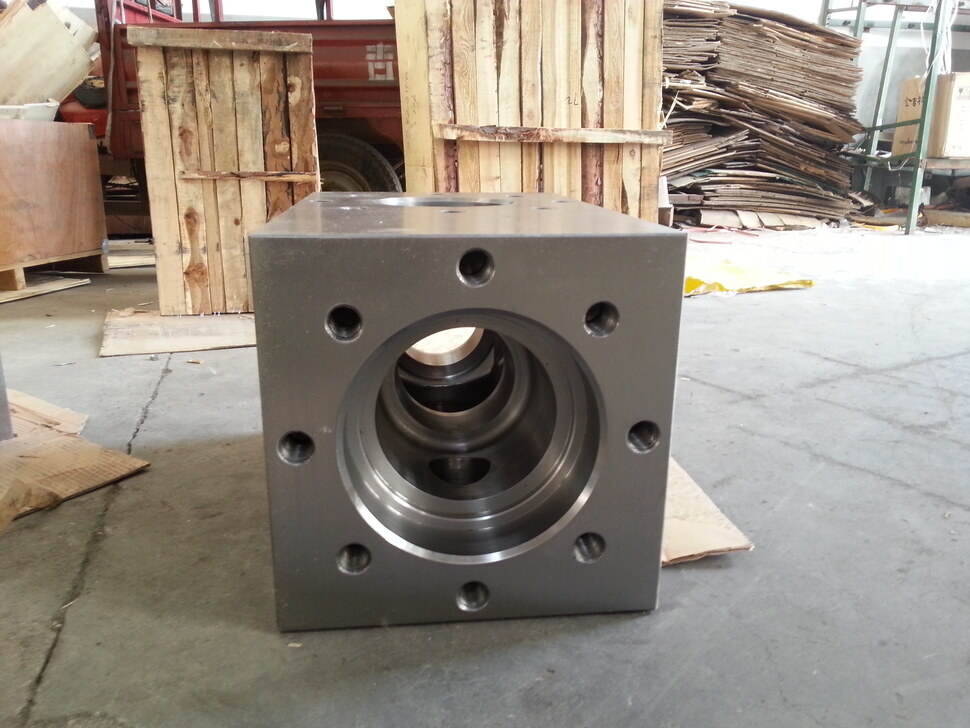
The L - type fluid end module adopts a split - type design. Two fluid end modules are arranged on the left and right, in an “L” shape, with the suction valve box and the discharge demco valve box designed separately. This design can not only adjust the flow rate of the pump by controlling the opening and closing of the inlet and outlet valves to meet specific drilling requirements, but also makes it much easier to install and remove the valve guide device at the discharge end. If one of the fluid end modules is damaged, only that one needs to be replaced while the other can continue to be used,reducing the maintenance cost and time.The traditional pump fluid end module is usually of an integral structure. The suction valve and the discharge valve are arranged vertically in the same fluid end module. The internal space of the fluid end module is relatively compact, and the structure is more complex. For example, the F - series fluid end module has many components such as gland covers and cylinder covers,and it requires more operating steps and time for installation and disassembly.
II. Advantages of the L - type Fluid End Module
Interchangeable PartsIn the traditional pump fluid end module, components such as gland covers and cylinder covers are usually not interchangeable,which increases the complexity of production and maintenance. In the production process, separate molds and processing techniques need to be designed for different components, increasing the production cost. In contrast,the L-type fluid end module combines the original gland cover and cylinder over into a thread pair(valve cover pressure cylindeer and threaded flange),connected by ACME threads.In this way,all the valve covers and thread pairs at the suction end and the discharge end,including the double-ended studs and nuts for connection and fastening,can be interchanged,reducing the workload of maintenance and the complexity of production and manufacturing.
Maintenance ConvenienceWhen maintaining the traditional pump fluid end module, many components need to be disassembled, such as gland covers, cylinder covers, and guide bushings. The connections between these components are relatively complex, and it is easy to cause damage during disassembly and assembly. For example, when replacing the guide bushing for mud pump liners, the gland cover or cylinder cover needs to be removed. Frequent installation and disassembly of the gland cover can easily damage the gasket, and the serrated threads inside the fluid end module are also prone to damage. If the threads cannot be repaired, the entire fluid end module needs to be replaced, resulting in a high maintenance cost. However, for the L - type fluid end module, since the suction valve box and the discharge valve box are separated, maintenance operations can be more targeted, and there is no need to disassemble a large number of irrelevant components like in the traditional fluid end module. For example, when replacing the guide bushing, just unscrew the valve cover pressure cylinder, pull the handle on the valve cover by hand, take out the valve cover together with the guide flange, then take out the gasket, and then replace the guide bushing outside the fluid end module. Installation is carried out in the reverse order, which greatly improves the maintenance efficiency and reduces the maintenance difficulty.
Optimized Guide DeviceThe guide devices of the suction valve and the discharge valve in the L - type fluid end module are the same as the guide flange, solving the problem of the traditional suction guide device having many structural parts and being troublesome to disassemble and assemble. The guide bushing is not easy to wear. When the guide flange is damaged due to frequent disassembly of the guide bushing, only the guide flange needs to be replaced, and the valve cover, threaded flange, and valve cover pressure cylinder can remain intact.
III. Maintenance, Inspection and Servicing
Appearance InspectionRegularly (such as daily or weekly, determined according to the usage frequency) inspect the appearance of the L - type fluid end module to check for signs of liquid leakage, including areas around the valve cover and flange connections. Check whether there is corrosion, deformation, or cracks on the surface of the fluid end module.
Internal CleaningAfter the drilling pump stops working, regularly clean the inside of the L - type fluid end module. Solid particles in the drilling fluid tend to deposit in the fluid end module, especially at the valve seats and inner - cavity corners. Special cleaning tools and cleaning fluids can be used to remove the deposited solid particles and dirt. The choice of cleaning fluid should be based on the composition of the drilling fluid and the material of the fluid end module to avoid corrosion of the fluid end module by the cleaning fluid. For example, for drilling fluids containing acidic components, alkaline cleaning fluids can be used for neutralizing cleaning.
Valve Flexibility CheckRegularly check whether the opening and closing of the valve are flexible. Manually operate the valve (ensuring safety) and feel whether the movement of the valve stem is smooth. If the valve movement is found to be inflexible, it may be caused by factors such as valve stem wear, spring failure, or blockage by solid particles. For minor blockages, the valve can be disassembled to remove the solid particles. For worn valve stems or failed springs, they should be replaced in a timely manner.
Valve Sealing Check and ReplacementRegularly check the sealing performance of the valve by observing whether there is wear, corrosion, or impurity accumulation on the contact surface between the valve seat and the valve disc. Once the sealing performance is found to decline, the valve seat or valve disc should be replaced in a timely manner. When replacing the valve sealing components, ensure correct installation, use appropriate tools to tighten the connecting parts according to the specified torque to ensure a good sealing effect.
Sealing Element Inspection Closely monitor the condition of the bonnet seal bop and piston sealing elements. Check whether the sealing elements have aging, deformation, or cracking. For the valve cover sealing elements, check whether the gaskets have extrusion, hardening, or softening phenomena. For the piston sealing elements, check whether the sealing rings have wear, scratches, or loss of elasticity. If problems are found with the sealing elements, they should be replaced in a timely manner to avoid drilling fluid leakage. When replacing the sealing elements, select products of the same specifications and materials as the original ones. When installing the sealing elements, ensure that the installation surface is clean and flat to avoid scratching the sealing elements. For rubber sealing elements, pay attention to avoid over - stretching during the installation process to prevent damage to the elasticity of the sealing elements. For example, when installing the piston sealing ring, a special installation tool can be used to slowly put the sealing ring on the piston to ensure its correct position.
Lubrication System MaintenanceIf the fluid end module is equipped with a lubrication system, regularly check the working status of the lubrication system. Check the oil level and quality of the lubricating grease or lubricating oil to ensure it is sufficient and not contaminated. Replace the lubricating grease or lubricating oil regularly according to the requirements of the equipment instruction manual. At the same time, check whether the pipelines of the lubrication system are unobstructed and whether the lubrication points can supply oil normally. For example, for an automatic lubrication system, check whether components such as the oil pump and distributor are working properly.
Cooling System Maintenance
For the L - type fluid end module equipped with a cooling system (such as a water - cooled jacket or air - cooling device), regularly check the operation of the cooling system. For the water - cooled jacket, check the flow rate, temperature, and water quality of the cooling water. Ensure that the flow rate of the cooling water is stable, the water temperature is within an appropriate range, and the cooling water does not cause scaling or corrode the pipelines. For the air - cooling device, check the rotation speed of the fan and whether the air vents are unobstructed to ensure good ventilation and effective heat dissipation of thefluid end module.
Read More


 Language :
 English
 Русский
 عربي
عربي
 GET A QUOTE


 IPv6 network supported