What is a drilling mud decanter centrifuge?
May 27, 2025
Ⅰ. Equipment Definition
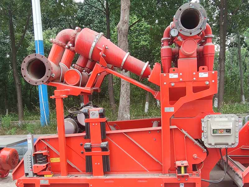
The Drilling Mud Decanter Centrifuge is a critical solid-liquid separation device in oil and gas drilling operations. It is primarily used for high-efficiency centrifugal separation of drilling mud (also known as drilling fluid), achieving graded treatment of solid particles in the mud and recycling of the liquid phase. This optimizes mud performance, reduces waste discharge, and saves costs.
Ⅱ. Core Functions
Solid Phase Grading Treatment
Separates solid particles of different sizes (such as cuttings and rock debris), typically capable of separating particles ≥2–5 microns (specific to equipment models and operating conditions).
Differentiates between "coarse solids" (to be discarded) and "fine solids" (retained in the mud to maintain performance).
Liquid Phase Recycling
Recovers the liquid phase in the mud (base fluid, chemical agents, etc.), reducing the amount of fresh mud preparation and material costs.
For oil-based mud or environmentally sensitive scenarios, liquid recycling minimizes environmental pollution.
Mud Performance Optimization
Adjusts mud density, viscosity, and rheological properties by controlling solid content and particle size distribution to meet process requirements for different drilling stages (e.g., drilling, cementing).
Ⅲ. Working Principle
Centrifugal Separation Mechanism
The equipment consists of a horizontal drum (rotating at high speed, 1,500–4,000 RPM) and an internal scroll conveyor.
Drilling mud enters the drum center and, under centrifugal force , solid particles settle on the drum wall and are pushed to the conical end by the scroll conveyor; the liquid forms an inner liquid ring and discharges from the overflow port at the opposite end of the drum.
Key Parameter Control
Drum Speed: Higher speeds generate greater centrifugal force and higher separation precision (suitable for fine particle separation).
Weir Height: Adjusts liquid residence time, affecting separation efficiency and liquid clarity.
Differential Speed (Speed Difference Between Drum and Scroll): Controls solid conveying speed to avoid over-compression or blockage.
Ⅳ. Typical Application Scenarios
Land Drilling:Processes water-based and oil-based mud, separates cuttings, and recovers useful solids like bentonite and barite.
Offshore Drilling:Meets environmental regulations (e.g., MARPOL Convention), reduces mud waste discharge, and adapts to space constraints on offshore platforms.
Horizontal/Directional Drilling:Handles high-viscosity and high-solid-content mud, maintains wellbore cleanliness, and prevents stuck pipe risks.
Waste Treatment:Reduces the volume of waste mud, lowering solid waste transportation and disposal costs.
Ⅴ. Technical Advantages
High Efficiency and Energy Saving:Processing capacity ranges from 30–150 m³/h (model-dependent), with energy consumption 30% lower than traditional filtration equipment.
Automated Control:Integrated PLC control system real-time monitors mud parameters (e.g., density, flow rate) and automatically adjusts operating parameters like speed and differential speed.
Wear-Resistant Design:Drums and scrolls are made of wear-resistant materials (e.g., tungsten carbide coatings, high-chromium cast iron) to extend service life and withstand high-sand-content mud environments.
Environmental Compliance:Reduces harmful substances (e.g., heavy metals, oil) in mud waste, meeting environmental standards worldwide (e.g., EPA in the U.S., CLP Regulation in the EU).
Ⅵ. Key Selection Parameters
Drum Dimensions
Diameter (e.g., 350mm, 450mm, 650mm): Larger diameters enable higher processing capacity, suitable for large-scale drilling operations.
Length-Diameter Ratio (L/D): A higher ratio improves separation precision, ideal for fine particle separation.
Processing Capacity
Maximum mud processing capacity (m³/h): Must match the flow rate of the drilling fluid circulation system.
Separation Precision
Minimum separable particle size (microns): Selected based on solid control requirements for drilling processes (e.g., deeper wells require higher precision).
Drive Mode
Variable Frequency Drive (VFD): Enables flexible speed adjustment to adapt to different mud conditions.
Ⅶ. Maintenance Considerations
Daily Inspections
Monitor bearing temperature and vibration values to prevent downtime due to mechanical failures.
Clean solid deposits on the drum inner wall and scroll conveyor to reduce wear.
Regular Maintenance
Replace gearbox lubricating oil every 500–1,000 hours and check the clearance between the scroll and drum (adjust or replace if worn).
Perform non-destructive testing (e.g., ultrasonic flaw detection) on wear-resistant components to assess wear levels.
Ⅷ. Types
Drilling mud decanter centrifuges can be classified into various types based on different criteria. Below are common classifications and their characteristics:
By Separation Precision (Minimum Separable Particle Size)
Medium-Speed Centrifuge(5–40 microns):Primary separation for removing larger cuttings, commonly used in initial mud purification.
High-Speed Centrifuge(2–5 microns):Fine separation for mud containing fine particles (e.g., bentonite, barite), suitable for deep wells with high mud performance requirements.
By Drum Structure
1.Cylindrical Centrifuge
Features: Cylindrical drum offers large separation space and high processing capacity but lower separation precision.
Application: Rapid processing of large mud volumes, suitable for primary solid control stages.
2.Conical Centrifuge
Features: Conical tail enhances solid compression via centrifugal force, improving separation efficiency and solid dewatering.
Application: Scenarios requiring high-dryness solid discharge (e.g., oil-based mud processing).
3.Cylindrical-Conical Composite Centrifuge
Features: Combines the large capacity of the cylindrical section with the high dewatering efficiency of the conical section, balancing processing capacity and separation precision.
Application: Most drilling scenarios, especially complex well conditions with high mud performance requirements.
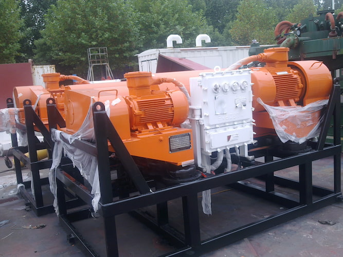
By Drive Mode
1.Single-Motor Drive Centrifuge
Structure: Driven by a single motor, with differential speed between the scroll and drum achieved via mechanical transmission (e.g., planetary gearbox).
Features: Simple structure and low cost, but limited differential speed adjustment range and flexibility.
2.Dual-Motor Drive Centrifuge
Structure: Drum and scroll are driven by independent motors, with differential speed controlled via frequency conversion.
Features: Real-time adjustment of differential speed based on mud characteristics, high adaptability, efficiency, and energy savings (e.g., with variable frequency motors).
3.Triple-Motor Drive Centrifuge
Structure: Adds an auxiliary motor to the dual-motor system for precise control of scroll torque and differential speed.
Features: Suitable for high-viscosity and high-solid-content mud, with higher reliability but increased cost.
By Explosion-Proof Rating
1.Standard Centrifuge
Application: Non-explosive environments (e.g., onshore conventional drilling).
2.Explosion-Proof Centrifuge
Features: Key components (motors, control systems) use explosion-proof designs (e.g., flameproof, increased safety types), compliant with international standards (ATEX, IECEx) or domestic standards (GB 3836).
Application: Explosive environments such as offshore drilling platforms and gas-containing well sites.
By Processing Capacity
Small Centrifuge(30–60 m³/h):Small drilling teams, laboratories, or low-flow mud circulation systems.
Medium Centrifuge(60–120 m³/h):Conventional onshore drilling, matching most rig mud circulation requirements.
Large Centrifuge(120–150 m³/h):Offshore platforms, large horizontal wells, or scenarios requiring rapid processing of large mud volumes.
Selection Recommendations
1.Based on Well Depth:
Shallow Wells (<3,000 meters): Choose medium-speed, cylindrical-conical composite centrifuges to balance cost and efficiency.
Deep Wells (>3,000 meters): Require high-speed, dual-motor drive centrifuges to ensure fine separation and stable mud performance.
2.Based on Mud Type:
Water-Based Mud: Standard centrifuges suffice.
Oil-Based/Synthetic-Based Mud: Must use explosion-proof, corrosion-resistant centrifuges with heating systems.
3.Based on Environmental Requirements:
Strict Environmental Areas (e.g., offshore drilling): Prioritize high-separation-precision centrifuges to reduce waste discharge, or use in conjunction with cutting dryers to further lower oil content.
Read More


 Language :
 English
 Русский
 عربي
عربي
 GET A QUOTE


 IPv6 network supported