facebook linkedin youtube whatsapp
National Unified Hotline :

+86 22 5807 5652

Email Us :

gm@geostarpe.com

#Language :

EnglishEnglish

内页banner

Search

Home

mud pump

  • What is the power equipment of a drilling rig?
    What is the power equipment of a drilling rig?
    Oct 17, 2025
    The power equipment of a drilling rig is the core device that supplies energy to the entire drilling system. Currently, the mainstream power types are divided into two major categories: diesel engine power and electric power, while hybrid power mode is adopted in some complex scenarios. Ⅰ. Diesel Engine Power Diesel engines are the traditional mainstream power source for onshore drilling rigs. They output mechanical energy through diesel combustion, which is then distributed to various working units via the transmission system. Core Advantages Strong independence: It does not rely on an external power grid and can operate independently in off-grid scenarios such as wilderness and deserts, with wide adaptability. High power density: The single-unit power can reach 1000-3000 kW, which can meet the high-load requirements of deep wells and ultra-deep wells. Fast start-up speed: It can start and stop quickly under emergency conditions (such as well kick and pipe sticking), with a response time of less than 30 seconds, ensuring operation safety. Key Equipment Main diesel engine: Mostly V-type 12-cylinder / 16-cylinder four-stroke diesel engines, equipped with a turbocharging system to adapt to harsh environments such as high altitude and high temperature. Diesel generator set: Provides low-voltage power (e.g., for control systems, lighting, and mud treatment equipment) to the auxiliary systems of the drilling rig, and usually operates in linkage with the main diesel engine. Applicable Scenarios Onshore remote oilfields, desert / plateau drilling, workover operations, and other scenarios without stable power grid coverage. Ⅱ. Electric Power Electric power is the mainstream development direction of modern drilling rigs, replacing traditional diesel engines through the "power grid supply + motor drive" mode. Core Advantages Low energy consumption and low pollution: Compared with diesel engines, energy consumption is reduced by 15%-25%, and there is no exhaust emission, which complies with environmental regulations. It is suitable for environmentally sensitive areas such as offshore and urban suburbs. High control precision: Variable-frequency speed-regulating motors (e.g., permanent magnet synchronous motors, asynchronous motors) are adopted, which can realize precise adjustment of drilling parameters (such as weight on bit and rotational speed), improving wellbore quality. Low maintenance cost: The motor has a simple structure, without vulnerable parts such as pistons and valves of diesel engines. The annual maintenance cost is reduced by 30%-40%, and the service life is extended to 15-20 years. Key Equipment High-voltage frequency converter: Converts high-voltage electricity from the power grid into variable-frequency power supply to control motor speed, serving as the "control core" of the electric power system. Drive motor: Divided into rotary table motors (driving drill string rotation), mud pump motors (driving mud circulation), and hoisting motors (driving traveling block for tripping operations). The single-unit power ranges from 500-2000 kW, configured according to load requirements. Emergency generator set: A backup power source when the grid power is interrupted, mostly a combination of a small diesel engine and a generator, ensuring uninterrupted operation of key equipment such as blowout preventers and mud pumps. Applicable Scenarios Offshore drilling platforms, large drilling rigs in onshore areas covered by power grids, and drilling in environmentally sensitive areas (e.g., coastal areas, suburban areas). Ⅲ. Hybrid Power Hybrid power combines the advantages of diesel engine power and electric power. The common mode is "diesel engine + battery energy storage system", which is mainly used in scenarios with large load fluctuations (e.g., alternating operations of tripping and drilling). Working Principle During low-load drilling operations (e.g., tripping), the diesel engine drives the generator to charge the battery; during high-load operations (e.g., high-pressure circulation of mud pumps), the battery and diesel engine supply power together, reducing the load fluctuation of the diesel engine and lowering fuel consumption. Core Advantage Fuel consumption is reduced by 20%-30% compared with pure diesel engines, and wear caused by frequent start-stop of the diesel engine is reduced, extending the equipment service life. Applicable Scenarios Onshore deep well drilling, workover operations, and other scenarios with frequent load fluctuations. Ⅳ. Maintenance Points For Diesel Engine Power 1.Regularly check the engine oil level and diesel filter element to prevent nozzle wear caused by impurities. 2.Replace the engine oil and air filter element every 200 hours to prevent high-temperature carbon deposition from affecting power output. 3.In cold environments, use anti-freezing diesel and add antifreeze to the water tank. For Electric Power 1.Regularly clean the cooling fan of the frequency converter and motor windings to prevent overheating caused by dust. 2.Test the motor insulation resistance monthly to avoid short circuits due to moisture. 3.After grid power interruption, check the battery capacity of the emergency generator to ensure normal emergency response.
    Read More
  • What is the circulation system of a drilling rig?
    What is the circulation system of a drilling rig?
    Oct 14, 2025
    Ⅰ. Surface Equipment Unit Mud Tank Function: A core container for storing, settling, and preparing drilling fluid, typically consisting of 3-5 independent tanks (suction tank, cleaning tank, reserve tank, weighting tank) with a single tank capacity of 50-100 m³. Mud Pump Function: Mostly a triplex single action reciprocating pump with an outlet pressure of 30-100 MPa and a displacement of 100-3000 L/min;It extracts drilling fluid from the suction tank, pressurizes it, and delivers it to the surface manifold, providing power for downhole circulation. Surface Manifold Function: A pipeline hub connecting the mud pump, swivel, and solids control equipment, composed of a standpipe, hose, mud gate valve, pressure gauge, etc.; It can switch the flow direction of drilling fluid via gate valves, and the pressure gauge monitors circulation pressure in real-time to prevent overpressure accidents. Swivel Function: A rotating sealing device installed under the traveling block, with the upper end connected to the hose and the lower end connected to the drill string; It enables synchronous rotation and fluid delivery, allowing the drill string to rotate at high speed while maintaining leak-free transportation of drilling fluid. Solids Control Equipment Function: A purification and filtration system for drilling fluid, classified into four levels by purification precision: 1.Shale shaker (removes large cuttings, screen size 0.2-1.5 mm); 2.Desander (removes sand particles, separation size 40-74 μm); 3.Desilter (removes mud particles, separation size 15-40 μm); 4.Centrifuge (removes colloidal particles, separation size 2-15 μm); It removes over 95% of solid particles from drilling fluid to ensure stable properties such as viscosity and density. Ⅱ. The Circulation Process of Drilling Fluid The circulation process of drilling fluid consists of three core stages, forming a complete closed loop, with specific procedures as follows: Stage 1: Drilling Fluid Descent (Surface → Bottom Hole, Power Delivery) 1.The mud pump extracts prepared drilling fluid from the suction tank, pressurizes it, and delivers it to the standpipe of the surface manifold; 2.The drilling fluid flows through the standpipe into the hose and then into the swivel; 3.The swivel guides the drilling fluid into the drill string bore through its rotating sealing structure, which flows downward along the hollow channels of the drill pipe and drill collar, eventually reaching the bottom hole bit; 4.The drilling fluid is ejected at high speed through the bit nozzles, forming a high-pressure jet to impact the bottom hole formation, assist the bit in breaking rock, and flush cuttings at the bottom. Stage 2: Drilling Fluid Ascent (Bottom Hole → Surface, Function Implementation) 1.The high-speed ejected drilling fluid wraps the broken cuttings at the bottom hole, forming a cuttings-mud mixture; 2.Driven by the continuous pressure of the mud pump, the mixture flows upward along the annulus, while completing three key tasks: Cooling the bit: Absorbing heat generated by bit rotation (bottom hole temperature can reach 150-200°C) and carrying it back to the surface through circulation; Stabilizing the wellbore: Clay particles in the drilling fluid form a 2-5 mm thick "mud cake" on the wellbore wall, plugging formation pores and preventing wellbore collapse; Balancing well pressure: Balancing formation pressure through drilling fluid column pressure to prevent blowouts or lost circulation; 3.After the cuttings-laden drilling fluid reaches the surface, it first enters the shale shaker for preliminary filtration of large cuttings larger than 0.2 mm in diameter. Stage 3: Purification and Regeneration (Surface Treatment, Recyclable Reuse) 1.The drilling fluid preliminarily filtered by the shale shaker flows into the desander, where sand particles with a diameter of 40-74 μm are separated by centrifugal force; 2.The drilling fluid with sand particles removed enters the desilter for further separation of mud particles with a diameter of 15-40 μm; 3.For high-requirement deep wells/complex wells, the drilling fluid needs to enter the centrifuge to separate colloidal particles with a diameter of 2-15 μm; 4.The purified drilling fluid flows into the cleaning tank, where technicians adjust its properties using testing instruments; 5.The qualified drilling fluid enters the suction tank, awaiting the next cycle to achieve zero or low-emission reuse. Ⅲ. Four Core Functions of the Circulation System 1.Carrying and removing cuttings: Preventing pipe sticking accidents 2.Cooling and lubricating the bit: Extending equipment service life 3.Stabilizing the wellbore and controlling well pressure: Ensuring wellbore safety 4.Transmitting downhole information: Supporting intelligent drilling
    Read More
  • What is a directional well in oil drilling?
    What is a directional well in oil drilling?
    Sep 17, 2025
    Directional drilling technology is one of the most advanced drilling technologies in the global oil exploration and development field today. It relies on special downhole tools, measurement instruments, and process technologies to effectively control the wellbore trajectory, guiding the drill bit to reach the predetermined underground target along a specific direction. This technology breaks the limitation of vertical wells, which "can only develop resources directly below the wellhead". By adopting directional drilling technology, oil and gas resources restricted by surface or underground conditions can be developed economically and effectively, significantly increasing oil and gas production and reducing drilling costs. In essence, a directional well is a drilling method that guides the wellbore to reach the target formation along a pre-designed deviation angle and azimuth. There are three main types of its well profiles: (1) Two-section type: Vertical section + build-up section; (2) Three-section type: Vertical section + build-up section + tangent section; (3) Five-section type: Upper vertical section + build-up section + tangent section + drop-off section + lower vertical section A horizontal well is a type of directional well. Conventional oil wells penetrate the oil reservoir vertically or at a shallow angle, resulting in a short wellbore section passing through the reservoir. In contrast, after drilling vertically or at an angle to reach the oil reservoir, the wellbore of a horizontal well is turned to a near-horizontal direction to remain parallel to the oil reservoir, allowing long-distance drilling within the reservoir until completion. Equipped with high-strength heavy-weight drill pipes (HWDP) for horizontal sections and wear-resistant PDC (Polycrystalline Diamond Compact) bits, the length of the reservoir-penetrating section can range from hundreds of meters to over 2,000 meters. This not only reduces the flow resistance of fluids entering the well but also increases production capacity several times compared to conventional vertical or deviated wells, facilitating enhanced oil recovery. Ⅰ. Application Scenarios 1. Overcoming Surface/Underground Obstacles Surface obstacles: When there are buildings, railways, lakes, or ecological protection zones above the reservoir, directional wells can be drilled outside these obstacles to reach the reservoir at an angle (e.g., development of oil and gas reservoirs around cities). Underground obstacles: When bypassing hazardous geological features such as underground caves, salt domes, and faults, shock-resistant and collapse-proof drill collars and high-pressure blowout preventers (BOP) are used in coordination to avoid drilling accidents like pipe sticking and blowouts. 2. Enhancing Production Capacity of Unconventional Oil and Gas Reservoirs Unconventional reservoirs such as shale gas and tight oil have "extremely low permeability". Vertical wells can only access a small area of the reservoir, leading to limited production capacity. However, horizontal wells traverse the reservoir horizontally over a distance of several hundred meters, increasing the contact area with the reservoir by dozens of times. The daily gas production of a single horizontal well can be 5 to 10 times that of a vertical well, making it a core technology for unconventional oil and gas development. 3. Reducing Development Costs Offshore oil and gas fields: Drilling a cluster of wells from a single offshore platform is far less costly than building a separate platform for each target, resulting in a 30% to 50% reduction in development costs. Mature oil fields: Through "sidETracking" of directional wells (drilling branches from the wellbore of an old well to develop remaining oil reservoirs in the surrounding area), there is no need to drill new vertical wells, significantly reducing investment. Ⅱ. Advantages and Disadvantages Compared with Vertical Wells Advantages 1.Strong resource coverage capability: It can develop offset reservoirs and scattered reservoirs that are inaccessible to vertical wells, improving the production efficiency of oil and gas reservoirs. 2.High single-well production capacity: Horizontal wells, in particular, greatly increase the contact area between the wellbore and the reservoir, offering significant advantages in the development of unconventional oil and gas reservoirs. 3.Superior cost-effectiveness: Cluster wells and multi-lateral wells, supported by integrated drilling rigs and matched drilling equipment (such as top drives and mud pumps), reduce surface occupation and platform construction costs, making them suitable for offshore and intensive development scenarios. Disadvantages 1.High technical complexity: It requires professional directional drillers, rotary steerable systems (RSS), and MWD (Measurement While Drilling) equipment, resulting in a much higher technical threshold than vertical wells. 2.High costs: The investment in a single directional well is usually 20% to 50% higher than that of a vertical well of the same depth (due to increased costs of tools, equipment, and labor). 3.High risks: The complex trajectory leads to high circulating resistance of drilling fluid and increased difficulty in wellbore stability, resulting in a higher incidence of accidents such as pipe sticking and wellbore collapse compared to vertical wells. 4.Long construction cycle: Frequent trajectory adjustments and data measurements are required, leading to a 30% to 60% longer construction cycle than vertical wells of the same depth. Ⅲ. Conclusion In summary, directional drilling represents a milestone in the evolution of oil drilling from simple vertical development to complex and precise development. Currently, in global oil and gas resource development, the application proportion of directional wells has exceeded that of vertical wells, making it one of the core technologies for ensuring oil and gas supply.
    Read More
  • Exploring the WH1612 Fluid End of Drilling Pumps: The Core Power Source in Drilling Engineering
    Exploring the WH1612 Fluid End of Drilling Pumps: The Core Power Source in Drilling Engineering
    Dec 10, 2024
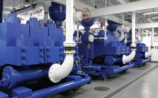
    In petroleum drilling engineering, the WH1612 fluid end of drilling pumps is a crucial component specifically designed for petroleum drilling projects. Throughout the entire drilling operation, it undertakes the important task of converting mechanical energy into the pressure energy and kinetic energy of drilling fluid, serving as a core component to ensure efficient and safe drilling. It is just like a powerful heart, continuously providing essential power for the entire drilling operation and ensuring that the drilling work proceeds smoothly. Today, let's explore this important piece of equipment together. Basic Structure and Components 
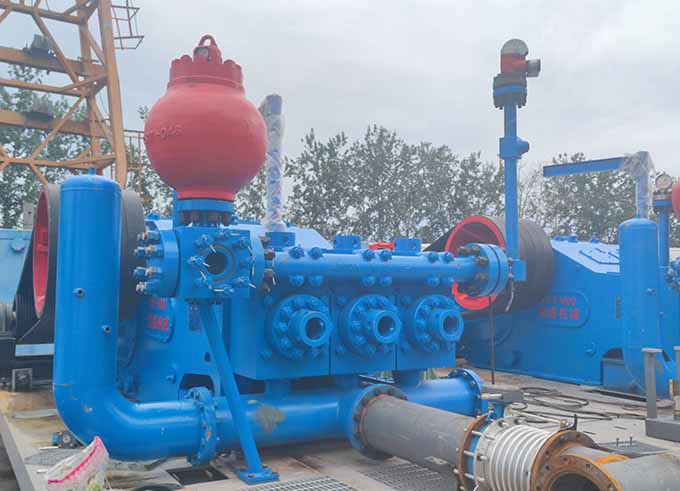
The WH1612 fluid end of drilling pumps mainly consists of several key components such as the cylinder liner, piston/plunger, mud pump fluid end module,suction valve, discharge valve, and sealing devices. The cylinder liner provides a stable space for the reciprocating motion of the piston or plunger. It is usually made of high-strength alloy steel, possessing excellent compressive and wear-resistant properties to cope with the harsh working environment and high-pressure impacts during the drilling process. The piston and plunger are the core moving parts for converting mechanical energy into the pressure energy of the liquid in the fluid end. Since they need to perform high-speed and reciprocating movements within the cylinder liner, extremely high requirements are placed on the wear resistance, sealing performance, and rigidity of their materials. Generally, high-quality alloy materials are selected and undergo precise processing and special treatments to ensure that they can maintain good working conditions during long-term operation. The mud pump fluid end module, which serves as the mounting carrier for the suction valve and the discharge valve, withstands tremendous pressure and liquid impact. It is manufactured using the upright integral forging process. This structure endows the mud pump fluid end module with extremely high strength and rigidity, effectively preventing deformation and rupture. Moreover, it improves the volumetric efficiency, enabling the drilling fluid to flow in and out of the cylinder liner more smoothly. The suction valve and the discharge valve are like the "gatekeepers" of the fluid end, precisely controlling the inflow and outflow of the drilling fluid. They are usually made of high-strength alloy materials and equipped with high-quality sealing parts to ensure that they can remain tightly closed under high pressure differences, preventing the backflow of the drilling fluid, thereby guaranteeing the working efficiency and stability of the fluid end. The sealing devices are the key defense lines to ensure the normal operation of the fluid end, responsible for preventing the leakage of the drilling fluid between various components. From the seals between the piston and the cylinder liner to those between the valves and the mud pump fluid end module, advanced sealing technologies and high-quality sealing materials such as rubber sealing rings and oil seals are adopted. These sealing parts have good high-temperature resistance, high-pressure resistance, wear resistance, and corrosion resistance properties, effectively reducing the leakage risk and improving the reliability and safety of the equipment.   Working Principle and Working Process The working principle of the WH1612 fluid end of drilling pumps is based on the reciprocating motion of the piston or plunger. When the mechanical energy transmitted from the power end drives the piston to move backward, the volume inside the cylinder liner increases and the pressure decreases. At this time, the suction valve automatically opens under the action of the pressure difference, and the drilling fluid is smoothly sucked into the cylinder liner. As the piston moves forward, the volume of the cylinder liner gradually decreases, and the pressure rises rapidly. The suction valve closes, and the discharge valve opens. The high-pressure drilling fluid is then transported through the discharge valve into the drilling pipeline and further flows to the bottom of the well, completing one working cycle. Through continuous repetition of this cycle, the WH1612 fluid end of the drilling pump can continuously provide a stable high-pressure drilling fluid flow for the drilling operation, realizing the circulation of the drilling fluid in the well, carrying the cuttings from the bottom of the well to the ground, keeping the wellbore clean, and simultaneously providing cooling and lubrication for the drill bit to ensure the smooth progress of the drilling process.   Performance Characteristics High-pressure and large-displacement capabilities: The WH1612 fluid end of drilling pumps is designed with outstanding high-pressure output capabilities, capable of meeting the requirements for high-pressure transportation of drilling fluid in complex drilling conditions such as deep wells and ultra-deep wells. Meanwhile, its relatively large displacement range can be flexibly adjusted according to different drilling operation requirements to ensure that the drilling fluid can circulate at an appropriate flow rate and improve drilling efficiency. Good sealing performance: Thanks to the advanced sealing structure and high-quality sealing materials, the fluid end can still maintain good sealing performance under high-pressure working conditions, effectively reducing the leakage of drilling fluid. This not only reduces the risk of environmental pollution but also improves the overall working efficiency of the equipment and reduces the energy loss and maintenance costs caused by leakage. High reliability and stability: By adopting high-strength materials and precise manufacturing processes, each component of the hydraulic end has excellent durability and anti-fatigue performance. Even during long-term and high-intensity drilling operations, it can operate stably, reducing the probability of malfunctions and providing reliable power support for drilling engineering, thus reducing the shutdown risks and maintenance costs caused by equipment failures. Strong adaptability: It can be flexibly configured and adjusted according to different drilling techniques and formation conditions. Whether it is conventional drilling, directional drilling, or horizontal drilling, the parameters of the fluid end can be optimized to make it perfectly match the entire drilling system and adapt to various complex and changeable drilling operation requirements.   Maintenance and Service Points Regular inspections: Establish a comprehensive regular inspection system to conduct a thorough inspection of all components of the fluid end. This includes checking the wear conditions of the piston and plunger, the sealing performance and opening flexibility of the valves, the scratching or corrosion status of the inner wall of the cylinder liner, and the aging and damage degree of the sealing parts. Through regular inspections, potential problems can be detected in a timely manner, and corresponding maintenance measures can be taken to avoid minor faults from developing into major ones. Lubrication management: Ensuring good lubrication of all moving parts of the fluid end is the key to extending the service life of the equipment. Strictly follow the equipment operation procedures, regularly add an appropriate amount of special lubricating oil to components such as the piston, plunger, and connecting rod, and check the working status of the lubrication system to ensure that the lubricating oil passages are unobstructed. Meanwhile, pay attention to the quality and replacement cycle of the lubricating oil and replace deteriorated or contaminated lubricating oil in a timely manner to ensure good lubrication effects. Cleaning and anti-corrosion: The environment at the drilling site is harsh, and the drilling fluid contains a large number of solid particles and corrosive substances, which are likely to cause pollution and corrosion to the components of the fluid end. Therefore, after each use, the fluid end should be cleaned in a timely manner to remove surface dirt and residual drilling fluid. For parts prone to corrosion, such as the mud pump fluid end module and piston rod, measures such as applying anti-corrosion coatings and installing anti-corrosion bushings can be taken to strengthen anti-corrosion protection and extend the service life of the components. Replacement of wearing parts: The piston, cylinder liner, valve rubber, etc. are wearing parts, and their service lives are affected by multiple factors. Reasonably determine the replacement cycle of wearing parts based on factors such as the usage frequency of the equipment, working pressure, and properties of the drilling fluid.   Common Malfunctions and Troubleshooting Methods Insufficient pressure: Possible causes may include failure of the piston or plunger seals, damage to the suction or discharge valves, blockage by foreign objects in the cylinder liner, etc. Check and replace damaged sealing parts and valves, clean out foreign objects in the cylinder liner, and ensure that all components are working properly to restore the pressure output of the fluid end. Unstable flow: This may be caused by air leakage in the suction pipeline, poor sealing of the valves, uneven movement of the piston or plunger, changes in the viscosity of the drilling fluid, etc. To address these issues, carefully check the connection parts of the suction pipeline and repair air leakage points; check and adjust the valve seals; check the moving parts of the piston or plunger to ensure smooth movement and eliminate flow fluctuation phenomena. Leakage problems: If leakage is found in the fluid end, first determine the leakage location. Common leakage points include areas around the sealing parts and valve connections. For leakage of sealing parts, replace the sealing parts in a timely manner; for leakage at valve connections, check and tighten the connection bolts or replace the sealing gaskets to ensure that the leakage problem is completely resolved.   As a core equipment component in drilling engineering, the performance quality and working status of the WH1612 fluid end of drilling pumps are directly related to the success or failure of the entire drilling operation.   The WH1612 drilling pump is the trademark and model of Cameron Company and has nothing to do with Tianjin Geostar Petroleum Equipment Co., Ltd. Tianjin Geostar mainly provides aftermarket spare parts for the WH1612 fluid end.
    Read More
  • Installation of Drilling Mud Pump
    Installation of Drilling Mud Pump
    Oct 22, 2023
    Drilling mud pump is the core equipment for petroleum drilling rig package, and following is the installation procedure of drilling mud pump unit. 1. The drilling pump and the base must be placed on a horizontal basis, the pump should be kept as horizontal as possible, and the horizontal deviation should not exceed 3mm, in order to facilitate the correct distribution of lubricating oil at the power end during operation.   2. The position of the pump should be as low as possible, and the position of the drilling mud tank should be raised as much as possible to facilitate suction.   3. The inner diameter of the suction pipe of the pump shall not be smaller than the inner diameter of the connection part of the pump. Before installation, it is necessary to clean the pump suction and pipelines, the suction line must not have air leakage, valves and elbows should be installed as little as possible, valves must use full-open valves. The length of the inlet pipe should be kept within the length range of 2.1m~3.5m to reduce the friction loss and inertia loss in the suction pipe, which is helpful. For suction, the suction line should be 300mm higher than the bottom of the drilling mud tank.   4. In order to smooth the operation of the pump and extend the life of the wear parts, the drilling pump needs to be equipped with a super charging pump. Between the inlet of the pump and the outlet of the charging pump. There should be a safety valve, which is adjusted to 0.5MPa, which protects the charging pump from damage in the event of overpressure in the suction pipe.   5. The connection between the suction pipe and the drilling mud tank cannot be directly opposite the drilling fluid return point above the drilling fluid pool, so as not to suck the drilling fluid tank bottom debris.   6. Firmly support all suction and discharge lines so that they are not subjected to unnecessary stress and reduce vibrations, which must never be caused by. There is not enough support to allow the line to hang on the pump.   7. In order to prevent damage to the drilling fluid pump due to excessive pressure, the relief valve must be installed at the outlet near the pump, and the safety valve must be installed before any valve, so that if the pump is accidentally started when the valve is closed, and the pump will not be damaged, the relief valve must be installed. The seamless steel pipe for the outlet is led directly to the mud pool, and this seamless steel pipe should have as few turns as possible. If turning, the elbow should be larger than 120°, do not lead the discharge end of the safety valve to the suction pipe of the pump with a pipe, so as to avoid high-pressure drilling fluid drainage when the safety valve is opened out causing unnecessary accidents.
    Read More
  • Drilling Mud Pump-The Heart of Oilfield Drilling Operation
    Drilling Mud Pump-The Heart of Oilfield Drilling Operation
    Oct 17, 2023
    Drilling pumps were formerly known as "mud pumps". If the whole drilling operation process is compared to human life activities, then the drilling pump, like the human heart, is the source of continuous circulation of drilling fluid from the ground to the bottom of the well, and then from the bottom of the well back to the surface. Drilling pumps are an important part of drilling equipment. In commonly used rotary drilling, it is to send the surface washing medium, drilling fluid, under a certain pressure, through the high-pressure hose, swivel and drill string center hole, straight to the bottom of the drill bit, so as to achieve the purpose of cooling the drill bit, removing the cut rock chips and transporting them to the surface. The commonly used drilling pump is piston type or plunger type, the crankshaft of the pump is driven by the power machine, and the crankshaft is driven by the crosshead and then driven by the piston or plunger in the pump cylinder to reciprocate. Under the alternating action of suction valve and discharge valve, the purpose of pressure delivery and circulation of drilling fluid is realized. During the drilling process, if the drilling pump does not work properly, a downhole drilling accident will occur, just like the human heart has stopped beating. The classification of drilling pumps can be divided into single-acting drilling pumps and double-acting drilling pumps according to the form of action, and can be divided into three cylinders and five cylinders according to the number of cylinders.
    Read More

Leave A Message

Leave A Message
If you are interested in our products and want to know more details, please leave a message here, we will reply to you as soon as we can.
Submit

Home

Products

whatsApp

contact