facebook linkedin youtube
National Unified Hotline :

+86 22 5807 5652

Email Us :

gm@geostarpe.com

#Language :

EnglishEnglish

内页banner

Search

Home

drilling mud pump

  • What is the F1600HL Electric Motor Driven Drilling Mud Pump?
    What is the F1600HL Electric Motor Driven Drilling Mud Pump?
    Apr 25, 2025
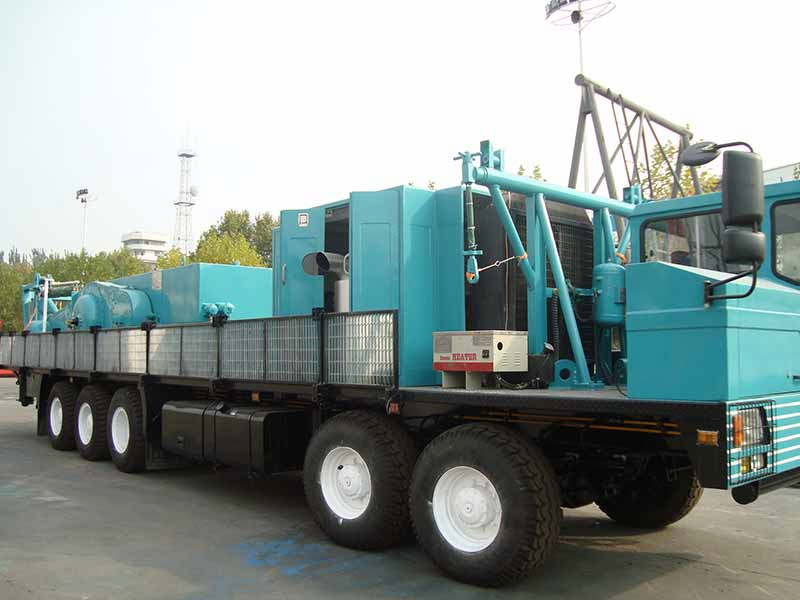
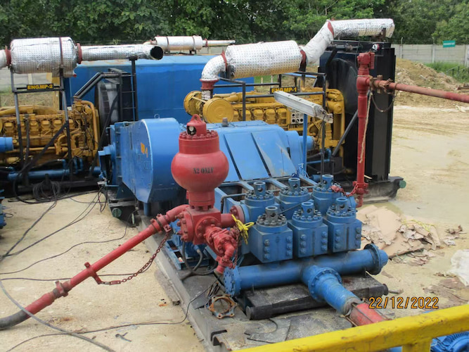
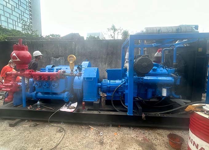
    The F1600HL Electric Motor Driven Drilling Mud Pump is a horizontal triplex single action piston pump, which is commonly used in equipment for oil and natural gas drilling and other fields. The following is the relevant introduction: Ⅰ. Structural Composition Power End Frame: Welded with steel plates and stress-relieved, it provides support and an installation foundation for other components of the power end. There is an oil sump and an oil circuit system inside. Gear Shaft: Usually composed of a gear, a shaft, and bearings, etc. The power output by the motor is first transmitted to the gear shaft. Crankshaft: It is an integral casting made of alloy steel, which is precisely processed and inspected by flaw detection. The power is transmitted to the crosshead through the connecting rod, realizing the conversion from rotational motion to reciprocating linear motion. Mud Pump Crosshead: It plays the role of connecting the crankshaft and the piston, mainly composed of components such as the crosshead body, slide block, and pin shaft, guiding the movement direction of the piston. 
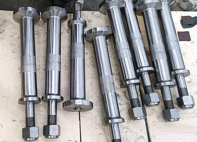
Intermediate Tie Rod: The packing adopts a double-layer sealing structure, which can effectively prevent mud leakage.
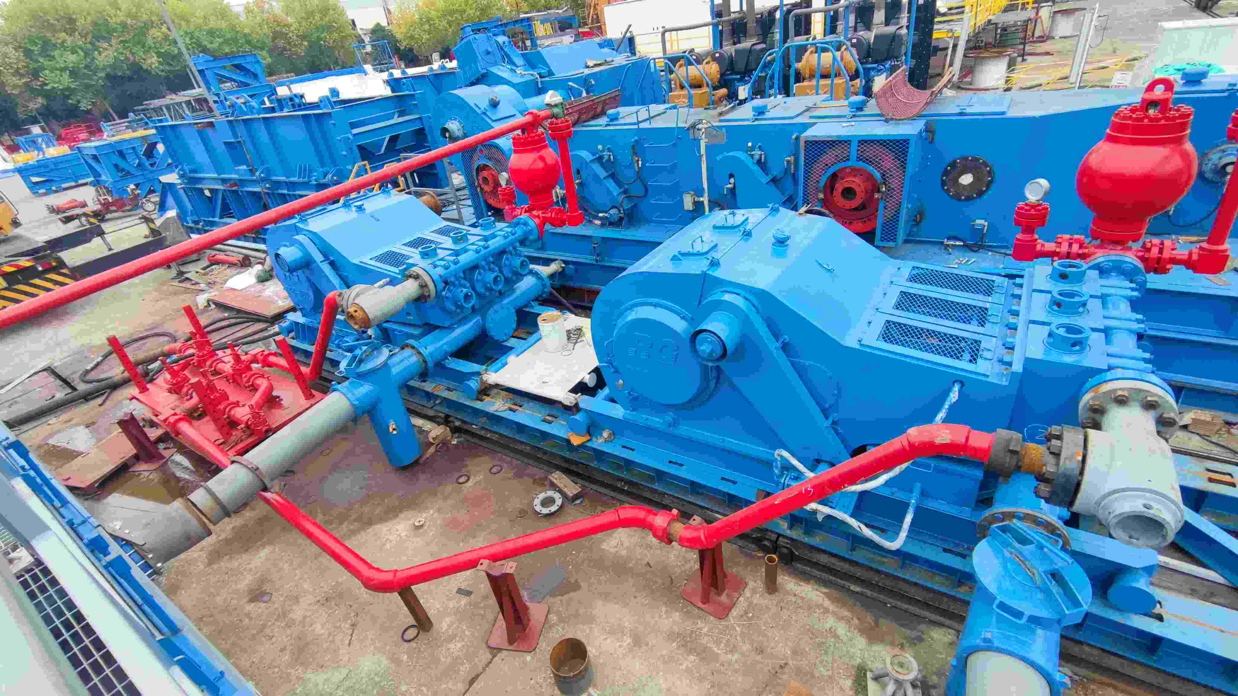
 Hydraulic End: Mud Pump Fluid End Module: The material is an alloy steel forging. With an "L" shaped cylinder design and a straight-through cylinder structure, that is, a valve-on-valve structure, it reduces the volume of the  Mud Pump Fluid End Module and improves the volumetric efficiency. Valve Assembly: API 7# valves are used, with a high-pressure valve structure with unloading grooves, which can effectively reduce the opening pressure of the valve and increase the service life of the valve. 
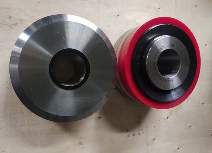
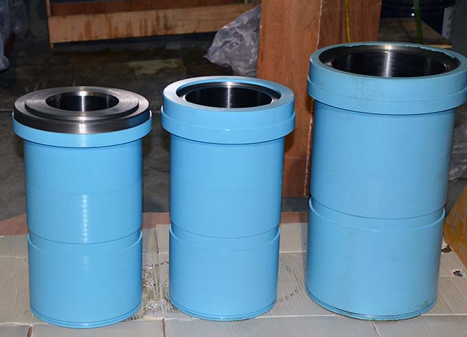
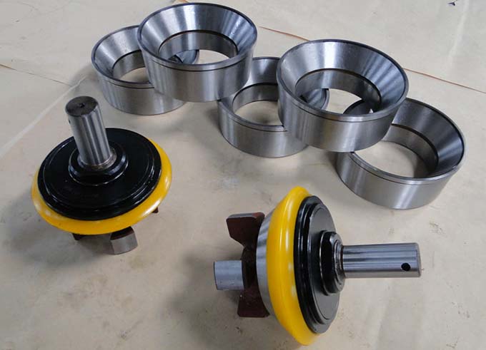
Mud pump Liner: Usually, a bimetallic cylinder liner is used. The inner lining is made of wear-resistant cast iron, and the inner hole surface has a high finish. It is sealed by cylindrical surface fitting and a rubber sealing ring and is tightened with a locking nut with anti-loosening function. 
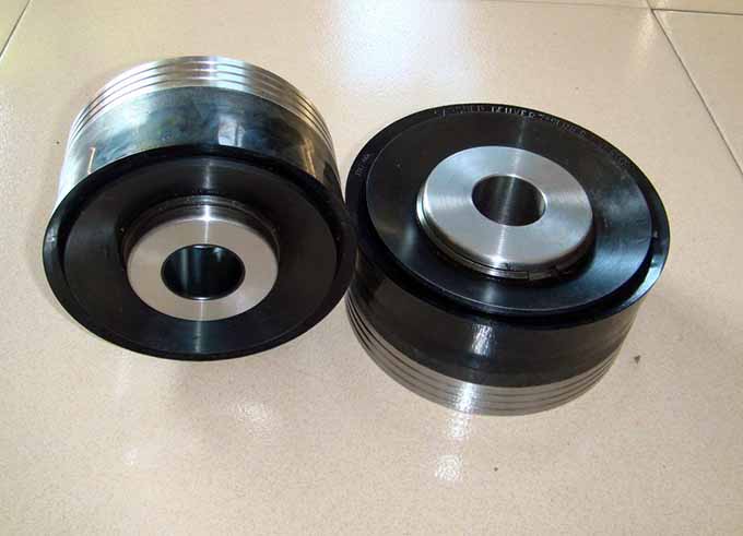
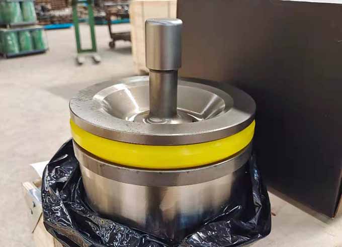
piston: A high-pressure piston resistant to high temperatures and oil-based drilling fluids is used, which has a good fit with the cylinder liner, ensuring the sealing performance and working efficiency of the mud pump. 
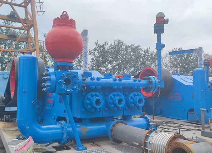
Suction and Discharge Manifold: A suction air chamber is usually installed on the suction pipeline to stabilize the suction pressure and reduce pressure fluctuations; a discharge air chamber, a shear pin safety valve, and a discharge strainer are respectively installed at the discharge port. Air Chambers: Including the suction air chamber and the discharge air chamber, which are filled with gas at a certain pressure. Their main function is to effectively reduce the pressure fluctuations in the suction and discharge systems, thus obtaining a more uniform liquid flow. Other Auxiliary Components: spray Pump Assembly: It includes components such as a spray pump, pipelines, and spray nozzles, which supply cooling and lubricating fluid (water) to the cylinder liner and piston of the hydraulic end for cleaning, cooling, and lubrication. Lubrication Mechanism: The lubricating oil is delivered to the working surfaces of components such as gears and bearings at the power end through an oil pump to form an oil film, reducing the friction coefficient and wear.Safety Valve: Such as a shear pin type high-pressure safety valve. When the pump outlet pressure exceeds the set value, the safety valve opens to release the pressure and protect the equipment. Ⅱ. Functions Circulating Drilling Fluid: During the drilling process of deep and ultra-deep oil wells, by continuously circulating the drilling fluid, it flushes the bottom of the well and carries the cuttings back to the surface, ensuring the smooth progress of the drilling work. Cooling and Lubrication: It provides cooling and lubrication for the drill bit, reducing the temperature of the drill bit during the drilling process, reducing wear, and extending the service life of the drill bit. At the same time, it helps to increase the drilling speed. Reinforcing the Wellbore: It enables the drilling fluid to form a mud cake on the wellbore wall, playing the role of reinforcing the wellbore wall and preventing the wellbore from collapsing. Ⅲ. Performance Advantages Comply with Standards: It is produced in strict accordance with API Spec 7K "Specification for Drilling and Well Servicing Equipment" and undergoes factory tests according to this standard, ensuring that the product quality and performance meet international standards and are suitable for various complex drilling conditions. High Pressure and Large Displacement: The maximum working pressure can reach 52MPa, and the displacement can reach 51.8L/s, which can meet the requirements of new drilling processes such as deep wells, ultra-deep wells, large-displacement horizontal wells, and high-pressure jet drilling, providing strong power support for drilling operations. Good Priming Performance: It has a long stroke and can be used at a low stroke rate, effectively improving the priming performance of the mud pump. Furthermore, it extends the service life of the vulnerable parts at the hydraulic end, reducing the maintenance cost and downtime of the equipment. Advanced and Compact Structure: The overall structure is advanced and compact, with a small volume, which is convenient for installation and transportation and can adapt to different drilling sites and operating conditions. Long Service Life of Vulnerable Parts: With a long stroke and the ability to operate at a low stroke rate, it effectively improves the priming performance of the mud pump, thus extending the service life of vulnerable parts at the hydraulic end such as cylinder liners, pistons, and valves, reducing the maintenance cost and downtime of the equipment. Easy Maintenance: The power end and the hydraulic end adopt an independent structural design, which is convenient for inspection, maintenance, and repair. The vulnerable parts at the hydraulic end such as cylinder liners, pistons, and valves are easy to replace without having to disassemble too many components, improving the maintenance efficiency. Ⅳ. Application Areas Oil and Natural Gas Drilling: It is suitable for onshore and offshore oil and natural gas drilling platforms, providing high-pressure mud for the drilling process and meeting the drilling requirements under different depths and complex geological conditions. Geothermal Drilling: It can be used in the drilling operations for geothermal resource development, pumping out the hot water or mud in the geothermal wells to realize the exploitation and utilization of geothermal resources. Geological Exploration Drilling: In the field of geological exploration, it is used for drilling geological structures, obtaining core samples, and other operations, providing data support for geological research. Ⅴ. Transmission Process The power transmission process of the power end of the F1600HL Electric Motor Driven Drilling Mud Pump is as follows: Motor Power Output: After the motor of the electric drive system is started, it generates rotational power. The output shaft of the motor is connected to the gear shaft, transmitting the power to the gear shaft. Gear Transmission: The gear on the gear shaft meshes with the bull gear. The rotation of the gear drives the bull gear to rotate. The bull gear is closely combined with the bull gear shaft through a key connection or other fixing methods, and the bull gear shaft rotates with the bull gear, thus transmitting the power from the gear shaft to the bull gear shaft assembly. Crankshaft Rotation: The rotational motion of the bull gear shaft is transmitted to the crankshaft, driving the crankshaft to rotate. The crankshaft is usually an integral casting made of alloy steel, which is precisely processed and inspected by flaw detection. Connecting Rod Transmission: The crankshaft is connected to the crosshead through the connecting rod. The rotational motion of the crankshaft is converted into the reciprocating linear motion of the crosshead through the connecting rod. During the movement of the connecting rod, one end moves in a circular motion with the crankshaft, and the other end drives the crosshead to move in a reciprocating linear motion in the slideway. Crosshead Driving the Piston: The crosshead is connected to the intermediate tie rod, and the intermediate tie rod is then connected to the piston. The reciprocating linear motion of the crosshead is transmitted to the piston through the intermediate tie rod, making the piston move reciprocally in the cylinder, thus providing power for the hydraulic end and realizing the suction and discharge of the mud. The power transmission process of the hydraulic end of the F1600HL Electric Motor Driven Drilling Mud Pump is as follows: Piston Reciprocating Motion: The crosshead at the power end drives the piston to move reciprocally in the cylinder through the intermediate tie rod. When the piston moves backward, a negative pressure is formed in the cylinder; when the piston moves forward, the mud in the cylinder is compressed, and the pressure increases. Suction Process: When the piston moves backward, the pressure in the cylinder decreases to form a vacuum. Under the action of atmospheric pressure, the mud pushes open the suction valve and enters the cylinder. The suction air chamber can stabilize the suction pressure and reduce pressure fluctuations, enabling the mud to enter the cylinder more smoothly. Discharge Process: When the piston moves forward, the mud in the cylinder is compressed, and the pressure increases. The suction valve closes, and the discharge valve is pushed open. The mud is forced out of the cylinder and is transported to the drill pipe through the discharge manifold and then sent to the bottom of the well. The function of the discharge air chamber is to reduce the pressure fluctuations in the discharge system, making the discharged mud flow more stable. Ⅵ. MaintenanceDaily Maintenance Check Operating Parameters: Check the operating parameters of the pump every day, including pressure, flow rate, motor current, and voltage, etc., to ensure that these parameters operate within the specified range. If any abnormal parameters are found, stop the machine immediately to check the cause. Check the Lubrication System: Before each start-up and during operation, check the oil level, oil quality, and oil temperature of the lubricating oil at the power end. The oil level should be maintained within the specified scale range. The oil quality should be clean without impurities and emulsification. Generally, the oil temperature should not exceed the specified value (usually 60 - 70℃). Regularly replenish or replace the lubricating oil, and at the same time, check the working status of the oil pump to ensure the normal oil supply of the lubrication system. Check the Cooling System: Check the working condition of the spray pump to ensure its normal operation, providing good cooling and lubrication for the cylinder liner and piston at the hydraulic end. Check whether there are blockages, water leaks, and other problems in the cooling water pipeline, and clean the blockages and repair the water leakage points in a timely manner. Check the Sealing Condition: Observe the sealing parts of the pump, including the cylinder liner seal at the hydraulic end, the valve seat seal, and the shaft seal at the power end, etc., to see if there is any mud leakage. If leakage is found, find out the cause in time and replace the damaged sealing parts. Clean the Equipment: Regularly clean the mud, oil stains, dust, and other sundries on the surface of the pump body to keep the equipment clean. Pay special attention to cleaning the dust on the motor cooling fins to ensure good heat dissipation of the motor. Regular Maintenance Replace Vulnerable Parts: According to the running time and wear condition of the pump, regularly replace vulnerable parts such as pistons, cylinder liners, valve seats, valve plates, and crosshead sliders, etc. It is generally recommended to check and replace these vulnerable parts after running for a certain number of hours (such as 500 - 1000 hours). Check Components at the Power End: Regularly open the inspection cover of the power end, check the wear condition of components such as gears, crankshafts, and connecting rods, measure the fit clearance of each component. If the wear exceeds the specified range, repair or replace it in time. At the same time, check the tightness of each connecting bolt to ensure a firm connection. Check Components at the Hydraulic End: Regularly disassemble the valve box at the hydraulic end, check the sealing performance and wear condition of the valve seat and valve plate, and clean up the sundries and mud deposits in the valve box. Measure the wear of the cylinder liner. If the inner diameter wear of the cylinder liner exceeds the specified value, replace it in time. Calibrate the Safety Valve: Regularly calibrate the safety valve to ensure that it can be reliably opened and closed within the specified pressure range to protect the safety of the equipment. Generally, the safety valve should be calibrated every six months or once a year. Maintain the Electrical System: Regularly check the insulation resistance of the motor to ensure good insulation. Clean the dust inside the frequency converter, control cabinet, and other electrical equipment, and check whether the connections of each electrical component are loose. If loose, tighten them in time. Maintenance in Special Situations Long-term Shutdown: If the pump needs to be shut down for a long time, comprehensive maintenance and protection should be carried out. First, empty the mud in the pump and rinse the hydraulic end and pipeline system thoroughly with clean water to prevent the mud from settling and solidifying. Then, apply anti-rust oil to the exposed parts of the power end and the hydraulic end to prevent rust. Finally, park the pump in a dry and well-ventilated place and turn the pump shaft regularly to prevent the parts from rusting and jamming. After Fault Repair: After the pump malfunctions and is repaired, focus on checking and testing the repaired parts. Ensure that the repaired parts are correctly installed and firmly connected, and that all performance indicators meet the requirements. At the same time, conduct a trial run of the entire pump unit, check whether the operation is stable and whether the parameters are normal. Only after confirming that there are no problems can it be put into formal use.    
    Read More
  • Troubleshooting and Repair of F-Type Drilling Mud Pumps
    Troubleshooting and Repair of F-Type Drilling Mud Pumps
    Dec 30, 2024
    During the production process of oil drilling, malfunctions frequently occur in the mud pumps of drilling rigs. To ensure the continuous and stable delivery of mud by the F-type drilling mud pump and maintain the normal operation of drilling, it is necessary to conduct troubleshooting and repairs. Today, let's delve into the common faults of the F-type drilling mud pump and the corresponding repair methods. I. Insufficient PressureAt the drilling site, the pressure of the mud pump suddenly fails to rise. The reasons for this situation are as follows:   Blockage in the suction pipeline: Rock debris and sediment mixed in the mud accumulate over time, easily clogging the suction pipe and hindering the smooth entry of mud into the pump body. When troubleshooting, first shut down the machine and then inspect the suction pipeline section by section to check for obvious accumulations of foreign matter. The repair method is quite simple. Disassemble the clogged section, clean it thoroughly, and then reinstall it as it was.Wear of pistons or cylinder liners: After long-term, high-intensity operations, wear and tear of  mud pump pistons and cylinder liners are inevitable. Excessive wear significantly reduces the sealing performance between the two, causing the pressure to fail to rise. We can preliminarily judge whether this is the cause of insufficient pressure by observing whether there are metal debris in the discharged mud. Once confirmed, new pistons and cylinder liners that match the specifications should be replaced. When installing, be sure to apply an appropriate amount of lubricant to ensure a tight fit between the piston and the cylinder liner.Fault in the safety valve: The safety valve is designed to prevent pressure overload during operation. If the safety valve gets stuck in the open position, the pressure will keep discharging. At this time, check the valve core and spring of the safety valve to see if there are any signs of seizure or breakage. If the valve core is stuck, clean the debris and readjust the spring pressure to restore normal operation.   II. Abnormal FlowFluctuations in flow, either sudden highs and lows or consistently low levels, can also severely disrupt the drilling process.   Air intake: If the suction end of the mud pump is not tightly sealed, air will enter. We will notice abnormal sounds and vibrations when the mud pump is running. Carefully inspect the connection parts of the suction pipe and the sealing gaskets. Once the air leakage point is found, tighten the bolts or replace the new sealing parts to prevent air from entering.Unstable pump speed: A fault in the power source may be the cause. Clogged fuel injection nozzles in diesel engines or phase loss in electric motors can lead to unstable pump speeds. Use professional instruments to measure the output power and speed of the power equipment and then solve the corresponding problems. For diesel engines, clean the fuel injection nozzles and calibrate the fuel injection pump; for electric motors, check the circuits to solve the phase loss problem and return the mud pump to a stable operating speed.Impeller damage: For F-type mud pumps with impellers, if the impeller has cracks or deformations, its ability to transport mud will be immediately weakened. We need to disassemble the pump casing to check the condition of the impeller. If the damage is minor, attempt to repair and calibrate it; if the damage is severe, replace it with a brand-new impeller to ensure the normal operation of mud transportation.   III. Abnormal Noise and VibrationHarsh noises and severe vibrations from the pump body are warning signs of malfunctions.   Unstable foundation installation: If the installation foundation of the mud pump is uneven or the anchor bolts are loose, abnormal sounds will be emitted during operation. We need to recalibrate the installation position, reinforce the anchor bolts, and place suitable shock-absorbing pads under the base of the mud pump.Bearing wear: It is common for the balls and raceways of bearings to become worn out and fail due to long-term, high-speed operation. If the mud pump has a high temperature and sharp noises, it can be basically determined that there is a problem with the bearings. At this time, first shut down the machine, then turn the pump shaft by hand to feel the resistance and clearance. If the bearings are severely worn, replace them without hesitation, and adjust the preload according to the specifications during installation.Foreign matter stuck in the pump: Small pieces of metal or rock debris that get into the mud pump and get stuck in key parts such as the impeller and piston will cause abnormal noises. We need to disassemble the relevant components of the pump body, clean out the foreign matter, and also check the source of the foreign matter entry and take protective measures to prevent a second intrusion.   Although the F-type drilling mud pump has a complex structure, as long as you are familiar with the troubleshooting ideas and repair methods for common faults, you can quickly respond to unexpected situations, minimize downtime, ensure the smooth progress of the drilling project, save costs, and steadily advance the project. Next time you encounter problems with the mud pump, you can conduct troubleshooting according to the above methods.    
    Read More
  • Unveiling the Heart of Mud Pump Operations: The Mighty Mud Pump Piston
    Unveiling the Heart of Mud Pump Operations: The Mighty Mud Pump Piston
    Apr 29, 2024
    In the intricate machinery of drilling rigs, where precision and reliability are paramount, the mud pump  piston emerges as a vital component, driving efficiency and performance to new heights. In this insightful exploration, we delve into the unique role of the mud pump piston, uncovering its significance and contributions to oilfield operations.   **Understanding the Mud Pump Piston**   At the core of every mud pump lies a series of valves and pistons working in tandem to facilitate the circulation of drilling fluid. The mud pump piston serves as the linchpin of this operation, regulating the flow of fluid within the pump and ensuring smooth and consistent performance. Unlike conventional pistons, mud pump pistons are meticulously designed to withstand the abrasive nature of drilling mud and the high pressures encountered in downhole environments.   **Engineering Excellence: The Anatomy of a Mud Pump Piston**   Crafted from high-strength materials such as steel, mud pump pistons undergo rigorous testing and quality control measures to ensure durability and reliability. Their unique design features precision-machined components, engineered to provide a tight seal and minimize fluid leakage during operation. Advanced coatings and surface treatments further enhance their resistance to wear and corrosion, extending their operational lifespan and reducing maintenance requirements.   **Optimizing Pump Performance**   The efficient operation of mud pumps is essential for maintaining drilling productivity and achieving project objectives. Mud pump  pistons play a pivotal role in optimizing pump performance by controlling fluid flow with precision and accuracy. Their ability to maintain consistent pressure and flow rates enhances drilling efficiency, reduces downtime, and minimizes the risk of equipment failure, ultimately translating into cost savings and operational excellence for drilling companies.   **Enhancing Safety and Reliability**   Safety is a top priority in the oil and gas industry, and mud pump pistons contribute to maintaining a safe working environment on drilling rigs. By preventing fluid backflow and maintaining pressure integrity within the pump system, these pistons help minimize the risk of accidents and spills, protecting personnel and equipment from harm. Their reliable performance instills confidence in operators, ensuring smooth and trouble-free drilling operations even in challenging conditions.   **Conclusion: The Power Behind the Pump**   In conclusion, the mud pump piston serves as the unsung hero of drilling operations, driving efficiency, reliability, and safety in the oilfield. Its robust construction, precision engineering, and performance-enhancing capabilities make it an indispensable component of mud pumps worldwide. By understanding the importance of mud pump pistons and investing in quality equipment, drilling companies can optimize their operations, mitigate risks, and achieve success in the demanding environment of the oil and gas industry.
    Read More
  • Exploring the Vital Role of F1600 Mud Pump Liners in Oilfield Operations
    Exploring the Vital Role of F1600 Mud Pump Liners in Oilfield Operations
    Apr 29, 2024
    In the realm of oilfield operations, where every component plays a crucial role in ensuring efficiency and productivity, the F1600 mud pump liner stands as a testament to engineering excellence. In this blog, we delve into the significance of F1600 mud pump liners, uncovering their importance and impact on drilling processes.   **Understanding the Mud Pump Liner**   First and foremost, let’s grasp the fundamental purpose of a mud pump liner. These liners serve as protective barriers within mud pumps, which are integral to drilling rigs. Mud pumps are responsible for circulating drilling fluid, or mud, downhole during drilling operations. This fluid serves various purposes, including cooling the drill bit, carrying drill cuttings to the surface, and providing hydrostatic pressure to prevent formation fluids from entering the wellbore.   **The F1600 Mud Pump Liner: A Key Component**   The F1600 mud pump liner is specifically designed to withstand the harsh conditions encountered in drilling operations. Constructed from durable materials such as high-grade steel or ceramic, these liners offer exceptional resistance to abrasion, corrosion, and erosion. Their robust construction ensures prolonged operational life, reducing downtime and maintenance costs for drilling companies.   **Enhancing Performance and Reliability**   One of the primary benefits of F1600 mud pump liners is their ability to maintain consistent performance under demanding conditions. By effectively sealing off the pump chamber, these liners minimize fluid leakage and pressure loss, allowing mud pumps to operate efficiently at high pressures and flow rates. This not only improves drilling performance but also enhances safety by reducing the risk of equipment failure.   **Optimizing Drilling Operations**   In the fast-paced world of oilfield drilling, time is of the essence. Any delays or disruptions can have significant financial implications. F1600 mud pump liners play a vital role in optimizing drilling operations by ensuring continuous and reliable fluid circulation. Their high-quality construction and precise engineering contribute to smoother drilling processes, allowing operators to achieve greater depths and higher drilling rates with confidence.   **Conclusion**   In conclusion, the F1600 mud pump liner represents a cornerstone of modern drilling technology. Its robust design, durability, and performance-enhancing capabilities make it an indispensable component in oilfield operations worldwide. By understanding the importance of F1600 mud pump liners, drilling companies can make informed decisions regarding equipment selection and maintenance, ultimately driving efficiency and productivity in the challenging environment of the oil and gas industry.
    Read More
  • Service Life Prediction of Mud Pump Piston: Insights and Considerations
    Service Life Prediction of Mud Pump Piston: Insights and Considerations
    Apr 14, 2024
    In the drilling industry, the mud pump piston is a critical component that plays a vital role in the efficient operation of the mud pump. Understanding the service life of the mud pump piston is essential for optimal performance and minimal downtime. In this blog, we'll explore the factors that influence the service life prediction of mud pump pistons.   Material Quality: The quality of the piston material significantly affects its service life. Durable and high-quality materials can withstand the harsh operating conditions.   Operating Conditions: Extreme temperatures, pressure and abrasive fluids can have a negative impact on the service life.   Maintenance and Inspection: Regular maintenance and inspections can help identify potential issues before they lead to premature failure.   Design and Manufacture: Well-engineered and manufactured pistons are more likely to have a longer service life.   Operating Parameters: Factors such as speed, load, and cycle times can affect the wear and tear on the piston.   Lubrication: Proper lubrication is crucial to reduce friction and extend the service life.   Usage Patterns: Heavy or continuous use can lead to earlier wear and tear compared to intermittent usage.   Condition Monitoring: Implementing a condition monitoring program can provide early warning signs of potential failure.   Predictive Analytics: Advanced analytics can help predict the remaining service life based on historical data and real-time monitoring.   By considering these factors, operators can make informed decisions to maximize the service life of the mud pump piston. Regular maintenance, proper operation, and timely replacement of worn-out components are key to ensuring uninterrupted drilling operations. Stay tuned for more insights on maintaining and optimizing the performance of your mud pump components.
    Read More
  • Selecting The Right Mud Pump Valve Seat: A Critical Decision
    Selecting The Right Mud Pump Valve Seat: A Critical Decision
    Apr 14, 2024
    In the world of drilling and well operations, the selection of a mud pump valve seat is a crucial choice that can impact the efficiency and performance of the entire system. A mud pump valve seat plays a vital role in ensuring the smooth operation of the drilling mud pump and preventing leaks and other issues. Here are some key factors to consider when selecting a mud pump valve seat:   Compatibility: It is essential to choose a valve seat that is compatible with your specific mud pump model. Different pumps may have unique requirements, and using an incompatible seat can lead to problems.   Material Quality: The quality of the material is critical. Look for a seat made from durable, corrosion-resistant materials that can withstand the harsh conditions of the drilling environment.   Leak Resistance: A good valve seat should provide a tight seal to prevent leaks, which can cause efficiency losses and potential safety hazards.   Durability: The seat should be able to withstand the wear and tear of regular use without failing prematurely.   Easy Maintenance: Select a valve seat that is easy to install and maintain, allowing for quick replacements when necessary.   Cost: While it's important not to compromise on quality, also consider the cost of the valve seat and ensure it fits within your budget.   Manufacturer Reputation: Choose a reputable manufacturer with a track record of producing high-quality components.   By taking these factors into consideration, you can make an informed decision when selecting a mud pump valve seat, ensuring the optimal performance and reliability of your mud pump system. Remember, a well-chosen valve seat is a small but essential part that can have a significant impact on the success of your drilling operations.
    Read More
  • The Key Factors Determining the Lifespan of Mud Pump Liners
    The Key Factors Determining the Lifespan of Mud Pump Liners
    Apr 02, 2024
    Introduction:   Mud pump liners play a vital role in the drilling industry, and understanding the factors that affect their lifespan is crucial for optimal performance and cost savings. In this blog, we'll explore the key elements that determine how long your mud pump liners will last.   Factors Determining Mud Pump Liner Lifespan:   Material Quality: The quality of the liner material significantly impacts its durability. Operating Conditions: Including pressure, temperature, and the type of drilling fluid. Corrosion Resistance: The liner's ability to withstand corrosion can extend its lifespan. Proper Installation: A well-installed liner ensures optimal performance and longevity. Regular Maintenance: Scheduled inspections, cleaning, and lubrication are essential. Fluid Properties: The composition and properties of the drilling fluid can affect the liner. Operating Pressure: High pressure can lead to quicker wear and tear. Particle Size: The size and amount of particles in the fluid can cause damage. Mechanical Stress: Vibration and other mechanical forces can impact the liner. Manufacturer Reputation: A reputable manufacturer often produces high-quality liners.   Conclusion:   By considering these factors and taking appropriate measures, you can maximize the lifespan of your mud pump liners, reducing downtime and maintenance costs. Stay vigilant and keep these factors in mind to ensure the long-term performance of your drilling mud pump. If you have any questions or additional insights, feel free to share in the comments below.  
    Read More
  • The Essential Guide to Selecting the Right Mud Pump Piston Rod
    The Essential Guide to Selecting the Right Mud Pump Piston Rod
    Apr 01, 2024
    Mud pump piston rod is one of the most commonly used mud pump parts, so selecting the right one is crucial for operation of drilling mud pump. In this blog, we'll explore the key factors you need to consider to make the best choice. First and foremost, material selection plays a vital role. Look for piston rods made from high-strength alloys that can withstand the harsh conditions of the drilling environment. Durability is paramount to ensure long-lasting performance. Size and dimensions are also important. The piston rod must fit precisely within the mud pump to ensure smooth operation and minimal wear and tear. Make sure to choose the correct size based on your specific pump model. Consider the load and pressure requirements of your application. The piston rod needs to be capable of handling the anticipated forces without failure. Quality of manufacturing is another critical factor. Look for a manufacturer with a reputation for producing high-quality piston rods that meet or exceed industry standards. It's also worth considering additional features such as corrosion resistance and surface treatments to enhance durability and performance. Finally, don't forget to factor in cost. While it's important to choose a high-quality piston rod, it's also essential to stay within your budget. In conclusion, selecting the right mud pump piston rod requires careful consideration of material, size, load capacity, quality, and cost. By taking these factors into account, you can ensure optimal performance and reliability of your mud pump.   
    Read More
  • 7 Proven Strategies to Extend the Service Life of Mud Pump Valve Seats
    7 Proven Strategies to Extend the Service Life of Mud Pump Valve Seats
    Mar 22, 2024
    Introduction: Mud pump valve seats are essential components in drilling operations, ensuring the smooth flow of drilling fluids under demanding conditions. However, frequent wear and tear can lead to premature replacement, causing downtime and increased costs. In this blog post, we'll explore seven effective strategies to maximize the service life of mud pump valve seats, helping you optimize operational efficiency and minimize maintenance expenses.   Keywords: mud pump valve seats, service life extension, valve seat maintenance, drilling operations   1. Choose the Right Valve Seat Material:    - Selecting the appropriate valve seat material is crucial for longevity. Consider factors such as temperature, pressure, and fluid composition to choose between rubber, polyurethane, or steel valve seats.   2. Implement Proper Installation Techniques:    - Ensure that mud pump valve seats are installed correctly, following manufacturer guidelines and recommendations. Proper installation prevents premature wear and ensures optimal performance.   3. Maintain Optimal Operating Conditions:    - Monitor and maintain optimal operating conditions, including fluid viscosity, temperature, and pressure. Operating within recommended parameters reduces stress on valve seats and prolongs their service life.   4. Conduct Regular Inspections:    - Schedule routine inspections to detect early signs of wear, erosion, or damage to mud pump valve seats. Prompt identification allows for timely maintenance or replacement, preventing costly downtime.   5. Clean Valve Seats Regularly:    - Develop a cleaning schedule to remove debris, solids, and contaminants from mud pump valve seats. Clean seats facilitate proper sealing and prevent abrasive particles from accelerating wear.   6. Use Protective Coatings or Liners:    - Consider applying protective coatings or liners to mud pump valve seats to enhance their resistance to abrasion, corrosion, and erosion. These coatings can significantly extend the service life of valve seats in harsh drilling environments.   7. Train Personnel on Maintenance Best Practices:    - Provide comprehensive training to drilling personnel on proper maintenance procedures for mud pump valve seats. Educated operators can identify issues early, perform maintenance tasks effectively, and contribute to prolonged service life.   Conclusion: Maximizing the service life of mud pump valve seats is essential for optimizing drilling operations and minimizing downtime and maintenance costs. By implementing the seven strategies outlined in this blog post – including selecting the right materials, proper installation, maintenance, and personnel training – drilling professionals can extend the lifespan of valve seats and ensure consistent performance in challenging environments. Incorporating these practices into your maintenance regimen will not only improve operational efficiency but also contribute to long-term cost savings and enhanced productivity.   By incorporating relevant keywords and optimizing your content for search engines, such as Google, you can increase the visibility of this blog post to your target audience, attracting readers interested in maximizing the service life of mud pump valve seats through effective SEO practices.
    Read More
  • Navigating Growth: The Gardner Denver Mud Pump Unveiled
    Navigating Growth: The Gardner Denver Mud Pump Unveiled
    Dec 27, 2023
    Introduction: In the heart of the oil and gas industry, the Gardner Denver mud pump emerges as a vital force, driving the success of drilling operations with its robust capabilities. This blog explores the key features, functions, and significance of the Gardner Denver mud pump in the dynamic landscape of well drilling.   1. **Essence of the Gardner Denver Mud Pump:**    The Gardner Denver mud pump stands tall as an indispensable component in the drilling process, ensuring the circulation of drilling fluids. This hydraulic powerhouse is designed to handle the challenging conditions of drilling environments, making it a linchpin in well construction.   2. **Key Components:**    - **Fluid End:**      The fluid end is a critical section of the mud pump responsible for pressurizing and pumping drilling fluid into the wellbore.      - **Power End:**      The power end provides the necessary force to drive the fluid end, typically powered by electric or diesel engines, ensuring a continuous and reliable pumping process.      - **Liner and Pistons:**      Liners and pistons work in tandem to create the reciprocating motion needed for pumping drilling fluids, contributing to the efficiency of the mud pump.   3. **Functions and Operations:**    - **Mud Circulation:**      The Gardner Denver mud pump maintains a continuous circulation of drilling fluid, carrying out essential functions like cooling the drill bit, carrying rock cuttings to the surface, and providing hydraulic pressure for efficient drilling.      - **Pressure Control:**      Precision in pressure control is a hallmark of the Gardner Denver mud pump, allowing drillers to adapt to varying geological conditions during the drilling process.   4. **Applications in Well Drilling:**    - **Oil and Gas Exploration:**      The mud pump plays a pivotal role in oil and gas exploration, facilitating the drilling process in diverse terrains and formations.      - **Geothermal Drilling:**      Its versatility extends to geothermal drilling, where the need for efficient mud circulation is paramount.   5. **Advancements and Innovations:**    - **Variable Frequency Drives (VFD):**      Integration of VFD technology enhances operational control, allowing for the adjustment of pump speed to match specific drilling conditions.      - **Digital Monitoring Systems:**      The adoption of digital monitoring systems provides real-time data on pump performance, enabling proactive maintenance and minimizing downtime.   6. **Environmental Considerations:**    - **Mud Recycling Systems:**      Gardner Denver mud pumps contribute to sustainable drilling practices by integrating mud recycling systems, reducing waste and environmental impact.      - **Efficiency for Lower Emissions:**      Enhanced efficiency in mud pump operations contributes to overall energy conservation and lower emissions during drilling activities.   Conclusion: As the Gardner Denver mud pump continues to evolve, it remains a stalwart companion in the journey of well drilling. Its reliability, efficiency, and adaptability underscore its significance in pushing the boundaries of exploration, making it an indispensable asset in the quest for energy resources beneath the Earth's surface.
    Read More
  • Installation of Drilling Mud Pump
    Installation of Drilling Mud Pump
    Oct 22, 2023
    Drilling mud pump is the core equipment for petroleum drilling rig package, and following is the installation procedure of drilling mud pump unit. 1. The drilling pump and the base must be placed on a horizontal basis, the pump should be kept as horizontal as possible, and the horizontal deviation should not exceed 3mm, in order to facilitate the correct distribution of lubricating oil at the power end during operation.   2. The position of the pump should be as low as possible, and the position of the drilling mud tank should be raised as much as possible to facilitate suction.   3. The inner diameter of the suction pipe of the pump shall not be smaller than the inner diameter of the connection part of the pump. Before installation, it is necessary to clean the pump suction and pipelines, the suction line must not have air leakage, valves and elbows should be installed as little as possible, valves must use full-open valves. The length of the inlet pipe should be kept within the length range of 2.1m~3.5m to reduce the friction loss and inertia loss in the suction pipe, which is helpful. For suction, the suction line should be 300mm higher than the bottom of the drilling mud tank.   4. In order to smooth the operation of the pump and extend the life of the wear parts, the drilling pump needs to be equipped with a super charging pump. Between the inlet of the pump and the outlet of the charging pump. There should be a safety valve, which is adjusted to 0.5MPa, which protects the charging pump from damage in the event of overpressure in the suction pipe.   5. The connection between the suction pipe and the drilling mud tank cannot be directly opposite the drilling fluid return point above the drilling fluid pool, so as not to suck the drilling fluid tank bottom debris.   6. Firmly support all suction and discharge lines so that they are not subjected to unnecessary stress and reduce vibrations, which must never be caused by. There is not enough support to allow the line to hang on the pump.   7. In order to prevent damage to the drilling fluid pump due to excessive pressure, the relief valve must be installed at the outlet near the pump, and the safety valve must be installed before any valve, so that if the pump is accidentally started when the valve is closed, and the pump will not be damaged, the relief valve must be installed. The seamless steel pipe for the outlet is led directly to the mud pool, and this seamless steel pipe should have as few turns as possible. If turning, the elbow should be larger than 120°, do not lead the discharge end of the safety valve to the suction pipe of the pump with a pipe, so as to avoid high-pressure drilling fluid drainage when the safety valve is opened out causing unnecessary accidents.
    Read More
  • Repair of Mud Pump Liners
    Repair of Mud Pump Liners
    Oct 22, 2023
    Cylinder liner is one of the main wear parts of drilling mud pump, which is often caused by serious abrasive wear and erosion wear to increase the inner diameter, and gradually form a large gap with the piston, resulting in mud leakage and pump pressure drop. At present, most of the cylinder liners used in oil fields are bimetal cylinder liners, although its inner layer is made of high chromium cast iron with high wear-resistant coating, but the service life is only 400~600 hours, and about 4500 pieces are consumed in Liaohe oilfield alone every year. The potential of expensive high chromium cast iron materials has not been fully realized. In the spirit of increasing revenue and saving expenditure, we have been carrying out trial repair of the scrapped cylinder liner of the 3NB-800 pump since February 1988. For example, its inner diameters of 130 mm and 140 mm were changed to 140 mm and 150 mm respectively. A total of 300 liners have been repaired and tried to be used in the Liaohe oilfield. The trial results show that its life span is as much as 500 hours, This is equivalent to the service life of a new liner, while the repair cost is only 50% of the price of a new liner. At present, there are four kinds of cylinder liners 130, 140, 150 and 160 mm commonly used in Liaohe Oilfield, and there is a high chromium cast iron with a thickness of 6 ~ 8 mm on the inner diameter surface. Usually, after the inner diameter is worn by 0.5~0.8mm, the cylinder liner fails. From this, it is possible to explore the potential of high-chromium cast iron and transform the obsolete cylinder liners into new cylinder liners with a larger inner diameter, as following; 1. Preparation before repair ( 1 ) Carefully select those centrifugally poured high chromium cast iron layers with uniform thickness from the waste cylinder liners, and in the inner diameter reprocessing and reheat treatment, it is possible to meet the requirements of technical conditions as repair objects. ( 2 ) Seal the repaired cylinder liner for cleaning, and use sandpaper or wire brush to remove rust spots and dirt on the inner and outer surfaces. ( 3 ) According to the technical requirements, repair welding is carried out on the defective parts of the outer surface and end of the cylinder liner. 2. Repair procedure There are two types of repair processes, one is to machine after heat treatment, and the other is to machine directly without heat treatment. (A) Method of machining after heat treatment (1) Select 130, 140, 150 mm cylinder liners with a layer thickness of 6~8 mm and place them in the furnace for protection annealing. When annealing, the cylinder liner should be placed upright in the heating furnace, and its stop end should be up. The hardness after annealing should be HRC 30~35. (2) After annealing, the machining process is carried out according to the inner diameter size requirements of the "new cylinder liner", and the grinding amount is left (the usual grinding allowance is 0.4 mm. (3) Protective quenching after machining processing, tempering should be carried out immediately after quenching, and the time of intermediate parking should not exceed 24 hours. The hardness after tempering should reach HRC60~64. (3) The inner diameter of the cylinder liner after tempering is ground and honed to meet the requirements of the drawing. (B) Method of direct machining without heat treatment The cylinder liner that has undergone hardness test of HRC60 or more is directly turned by special tools, and the cutting speed is controlled during procedure: At 10~20 meters per minute, the passing amount is 0.3~0.6 mm per revolution, the cutting depth is 0.5~1.0 mm, and the grinding amount is left. Its inner diameter is finally ground and honed to meet the requirements of the drawing. The cylinder liner repaired by the above method should be painted and oiled after passing the inspection according to the technical requirement, and packaged for later use.
    Read More
1 2
A total of2pages

Leave A Message

Leave A Message
If you are interested in our products and want to know more details, please leave a message here, we will reply to you as soon as we can.
Submit

Home

Products

whatsApp

contact