From Principle to Advantages: A Comprehensive Interpretation of Demco Mud Gate Valve
Feb 11, 2025
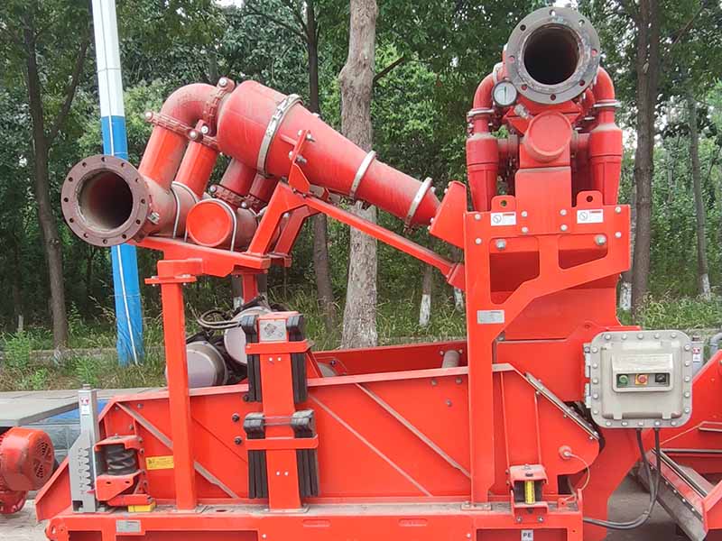
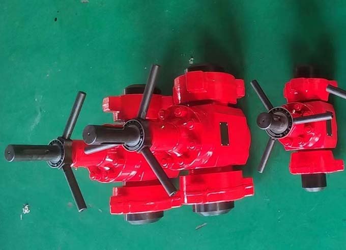
Demco Type Mud Gate Valve are top-notch designed gate valves in the oil and gas drilling market, specifically manufactured to meet the stringent requirements of oilfield applications. They are suitable for heavy-duty performance under harsh service conditions and are commonly found in various oilfield applications such as drilling riser manifolds, pump manifold stop valves, high-pressure mud lines, high-pressure and fracturing services, production manifolds, production gathering systems, and production flow lines.
I. Structural Design
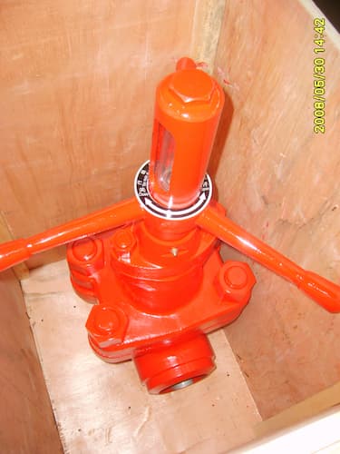
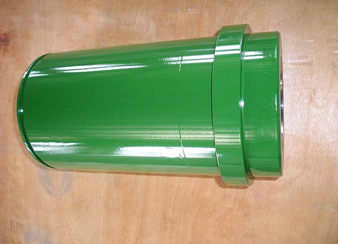
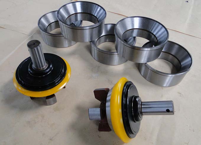
The mud gate valve mainly consists of a valve body, valve cover, valve seat, gate plate, valve stem, valve stem nut, handle, O-ring, etc. The design, manufacturing, flange connection form, inspection, and testing of the valve comply with the provisions of API Spec 6A standard, and the threaded connection form complies with the provisions of API 5B standard.
Valve Type: Usually designed as a parallel-slide gate valve, the gate plate is flat-shaped and moves perpendicular to the fluid flow path to control the fluid flow rate. This design allows the fluid to pass through unobstructed when the valve is open, reducing flow resistance and contributing to improving drilling efficiency.
Materials: It is made of high-quality materials such as carbon steel and stainless steel, which can withstand harsh conditions such as high temperature, high pressure, and mud scouring during drilling operations, ensuring the strength and durability of the valve and extending its service life.
Connection Methods: It provides various end-connection methods, such as threaded connection, welding, ferrule connection, and flange connection, etc. These can be selected according to different installation locations and pipeline system requirements, facilitating connection to the pipeline system of drilling equipment.
II. Working Principle
Manual Operation: By rotating the handwheel, the valve stem is driven to move linearly. The valve stem is connected to the gate plate, causing the gate plate to move up and down in the valve body. When the gate plate rises, the valve opens, and fluids such as mud can pass through the valve passage; when the gate plate descends, the gate plate fits tightly against the valve seat, blocking the fluid flow, thus achieving control over the flow rate and direction of the mud.
Remote Control: It can be equipped with a hydraulic or pneumatic actuator. The control system sends signals remotely to control the action of the actuator, which in turn drives the movement of the valve stem and the gate plate, enabling remote opening and closing of the valve to meet the demand for precise valve control in complex drilling environments.
III. Performance Characteristics
Full-Bore Design: The inner diameter of the valve passage is the same as that of the pipeline, allowing fluids such as mud to flow smoothly in the pipeline, reducing the pressure loss of the fluid at the valve, improving the circulation efficiency of the drilling fluid, and contributing to optimizing the drilling operation process.
Bi-Directional Sealing: It has a bi-directional sealing function, meaning that regardless of the direction of fluid flow, a good seal can be formed between the gate plate and the valve seat to prevent fluid leakage, ensuring well control safety during the drilling process and increasing the valve's applicability under different working conditions.
Maintainability: The valve cover is easy to disassemble. Internal parts can be inspected or replaced without removing the valve from the pipeline. This design is simple, quick, and easy to maintain without the need for special tools.
Diverse Pressure Ratings: It has a wide range of pressure ratings, such as 2000psi, 3000psi, 5000psi, 7500psi, etc., which can meet the mud transportation requirements in different pressure environments, being applicable to both shallow well and deep-well drilling.
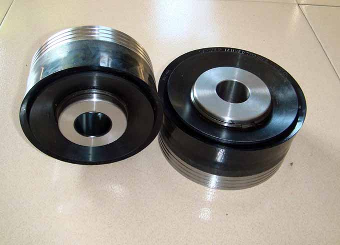
High Wear Resistance: Since mud often contains solid particles that can cause wear to the valve, components of the Demco mud gate valve that come into contact with the mud, such as the gate plate and valve seat, are usually made of wear-resistant materials such as cemented carbide and high-strength alloy steel. Through special surface treatment processes such as spraying and surfacing, the surface hardness and wear resistance are enhanced, extending the valve's service life and reducing maintenance and replacement costs.
IV. Application Fields
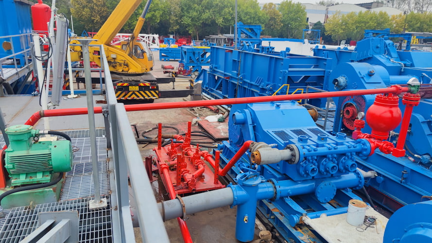
Oil and Gas Drilling: In drilling operations, it is used to control the flow of drilling mud, achieving operations such as mud circulation, discharge, and throttling, ensuring the pressure balance and stability of the wellbore during the drilling process, and preventing accidents such as blowouts.
Completion and Workover Operations: During well completion and workover processes, it is used to control the flow of fluids such as cement slurry and fracturing fluid, ensuring the smooth progress of the operations and effectively plugging and isolating the wellbore.
Petrochemical Pipeline Systems: In the pipeline systems of petrochemical production, it is used to control the flow of various fluids containing solid particles or corrosive media, such as crude oil transportation and slurry transportation during petroleum refining.
V. Functions of Accessories
Cut-off Function: It can quickly cut off the flow of mud in the pipeline. For example, during drilling operations, when it is necessary to repair, replace components, or handle faults in a certain section of the pipeline, the valve can be quickly closed to stop the mud from flowing, facilitating safe operations.
Flow Regulation: By changing the opening degree of the valve, the flow rate of the mud can be precisely controlled to meet the requirements of different working conditions. For example, in oil extraction, according to the drilling depth, formation conditions, and drill bit wear, the mud flow rate can be reasonably adjusted to ensure drilling efficiency and quality.
Backflow Prevention: It can effectively prevent the backflow of mud in the pipeline, avoiding damage to equipment and pipelines caused by mud backflow or affecting the normal operation of the entire process flow, ensuring the stability and safety of the pipeline system.
Reducing Pressure Loss: With a reasonable structural design, it can reduce the pressure loss of the mud in the valve, improve energy utilization efficiency, and reduce additional energy consumption and equipment load caused by excessive pressure loss.
VI. Storage and Installation
Storage: If the valve needs to be stored for a long time, it should be stored in a dry and ventilated indoor environment, avoiding direct sunlight and a humid environment. The inlet and outlet of the valve should be sealed with plastic sheets or other sealing materials to prevent dust and debris from entering. Regularly inspect and maintain the stored valve, and apply anti-rust oil to prevent rusting.
Installation: During installation, ensure that the valve is installed in the correct direction, is firmly connected to the pipeline, and has a good seal. Avoid collisions and damage to the valve during the installation process. After installation, conduct a pressure test and a sealing test to check whether the valve performance meets the requirements.
VII. Operation Precautions
Manual Operation: When operating the handwheel, apply force evenly. Do not use a force-increasing rod or excessive force to avoid damaging the valve stem, valve stem nut, or gate plate. Operate according to the marked opening and closing direction to avoid reverse operation.
Electric or Pneumatic Operation: Regularly check the control system, air source, or power supply of the electric or pneumatic device to ensure its normal operation. During the operation process, if any abnormal conditions are found, such as motor overload or cylinder air leakage, stop the operation immediately and conduct inspections and repairs.
Medium Requirements: Avoid mixing overly large particles or impurities into the mud to prevent wear and blockage of the valve's sealing surface and internal components. For mud containing corrosive media, select a valve with a suitable material according to the nature of the media and take corresponding anti-corrosion measures.
VIII. Fault Troubleshooting
1.Sealing Leakage
Problems with the Sealing Surface between the Gate Plate and the Valve Seat
Inspection Content: Check whether the sealing surface has wear, scratches, corrosion, or deformation. After long-term use, the scouring and wear of the mud may cause the sealing surface to become uneven, affecting the sealing effect.
Troubleshooting Method: Disassemble the valve, visually inspect the condition of the sealing surface, or use special detection tools such as a sealing surface flatness detection ruler. If the sealing surface is damaged, it is usually necessary to grind or replace the gate plate and the valve seat.
Aging or Damage of the Sealing Ring
Inspection Content: Check whether the sealing ring has aging, cracking, deformation, or damage. The sealing ring is prone to aging and damage when it is in a high-pressure, high-temperature, or corrosive medium for a long time.
Troubleshooting Method: Observe the appearance of the sealing ring and check its elasticity and integrity. If there are problems, replace the sealing ring in a timely manner to ensure that its material and specifications are the same as the original one.
Leakage at the Connection between the Valve Body and the Valve Cover
Inspection Content: Check whether the connecting bolts are loose and whether the sealing gasket is damaged. Loose bolts will increase the gap at the connection, and a damaged gasket will directly affect the sealing performance.
Troubleshooting Method: Use a torque wrench to check the bolt torque. If loose, tighten them according to the specified torque; disassemble and check the sealing gasket. If damaged, replace it with a new one.
2.Difficult Valve Operation
Sticking of the Valve Stem
Inspection Content: Check whether the valve stem surface has wear, corrosion, scratches, or impurities attached. The valve stem is in contact with the mud for a long time, and these problems are likely to occur, increasing the friction between the valve stem and the stuffing box.
Troubleshooting Method: Disassemble the valve stem, clean the surface impurities, and observe the wear situation. Slight wear can be polished and repaired, and severe wear requires replacement of the valve stem. At the same time, check whether the stuffing box is deformed or damaged and deal with it in a timely manner if there are problems.
Faults in the Transmission Components
Inspection Content: For manual valves, check whether the handwheel, valve stem nut, and other transmission components are worn, damaged, or jammed; for electric or pneumatic valves, check whether the motor, cylinder, gears, and other transmission components are working properly.
Troubleshooting Method: During manual operation, feel the resistance of the handwheel rotation and observe the movement of the transmission components; for electric or pneumatic valves, check whether the motor is powered on, whether the cylinder is supplied with air, and whether there are obvious signs of damage to each transmission component. If there are faults, repair or replace the damaged transmission components.
Jamming of the Gate Plate
Inspection Content: Check whether the gate plate is stuck due to impurities, agglomerates, or foreign objects in the mud, and whether there is excessive friction between the gate plate and the valve seat.
Troubleshooting Method: Disassemble the valve, clean the impurities and foreign objects around the gate plate and the valve seat, and check the fit clearance between the gate plate and the valve seat. If necessary, repair or adjust the gate plate and the valve seat.
3.Internal Leakage of the Valve
Damage to the Sealing Surface
Inspection Content: Similar to the method of checking the sealing surface for sealing leakage, focus on checking whether the sealing surface has small cracks, wear, or corrosion pits. These defects may cause the valve to be unable to seal completely when closed, resulting in internal leakage.
Troubleshooting Method: Conduct a sealing test using high-pressure water or gas, and observe whether there is any leakage inside the valve. If there is internal leakage, disassemble the valve to check the sealing surface and repair or replace it according to the degree of damage.
Deformation of the Gate Plate
Inspection Content: Check whether the gate plate is deformed due to long-term stress or uneven medium pressure. The deformed gate plate may not fit tightly against the valve seat, resulting in internal leakage.
Troubleshooting Method: Disassemble the gate plate, use professional measuring tools to check the flatness and dimensions of the gate plate. If deformation is found, correct or replace the gate plate according to the specific situation.
4.External Leakage of the Valve
Leakage of the Stuffing Box
Inspection Content: Check whether the packing is aging, worn, or improperly installed. The stuffing box is a key component to prevent leakage at the valve stem, and the performance and installation quality of the packing directly affect the sealing effect.
Troubleshooting Method: Observe whether there is mud seepage at the stuffing box. Disassemble the stuffing box and check the condition of the packing. If the packing is aging or worn, replace it with new packing and ensure that the packing is installed tightly and evenly.
Sand Holes or Cracks in the Valve Body
Inspection Content: Check whether there are sand holes, cracks, or other defects on the surface of the valve body. These defects may be caused by casting quality problems or long-term exposure to pressure, corrosion, and other factors.
Troubleshooting Method: Use methods such as visual inspection, penetrant testing, or ultrasonic testing to find sand holes or cracks on the valve body. For small sand holes, methods such as repair welding can be used; for cracks, the valve body generally needs to be replaced.
Read More


 Language :
 English
 Русский
 عربي
عربي
 GET A QUOTE


 IPv6 network supported