facebook linkedin youtube
National Unified Hotline :

+86 22 5807 5652

Email Us :

gm@geostarpe.com

#Language :

EnglishEnglish

内页banner

Search

Home

F type drilling mud pump

  • What is the spray system of the F-type drilling mud pump?
    What is the spray system of the F-type drilling mud pump?
    Apr 28, 2025
    The spray system of the F type drilling mud pump is mainly composed of components such as the spray pump, cooling water tank, and spray pipes. The following is an introduction to the advantages, working process, and pressure control of the spray system. Ⅰ. The F-type drilling mud pump spray system has the following main advantages:Efficient Cooling The spray system can accurately spray the cooling liquid onto the key heat-generating parts of the mud pump, such as the mud pump fluid end module and mud pump piston. Through the heat absorption and evaporation of the liquid, it can quickly take away a large amount of heat, effectively reducing the working temperature of these components and ensuring that the mud pump can still maintain stable performance under high-load operation conditions. Extended Component Lifespan The stable cooling effect helps to reduce the damage to the Mud pump fluid end module and piston caused by thermal fatigue and wear, thus prolonging their service life. At the same time, proper cooling can prevent the rubber seals from aging and failing due to overheating, maintain good sealing performance, reduce mud leakage, and thus reduce maintenance costs and replacement frequencies. Improved Mud Pump Efficiency When the key components are within the appropriate temperature range, the overall operation efficiency of the mud pump is improved. The cooling system can prevent the expansion and deformation of components caused by overheating, ensure the matching accuracy between components, make the power transmission of the mud pump smoother, reduce energy loss, and thus improve its volumetric efficiency and hydraulic efficiency. Improved Working Environment During the cooling process of the spray system, the humidity of the surrounding air will increase, which can reduce the dust flying around the mud pump, improve the air quality of the working environment, and be beneficial to the health of the operators. In addition, the lower equipment temperature also reduces the overall temperature of the working area, making the working conditions of the operators more comfortable. High Reliability The spray system of the F- type drilling mud pump usually adopts high-quality materials and advanced manufacturing processes, with good corrosion resistance and wear resistance, and can adapt to harsh drilling site environments. At the same time, the system has a simple and reasonable design, with high stability and anti-interference ability, reducing the downtime caused by system failures and improving the continuity and reliability of drilling operations. Easy Maintenance The structure of the spray system is relatively simple, and the layout of each component is reasonable, making it convenient for operators to conduct daily inspections, maintenance, and upkeep. For example, components such as nozzles and pipes are easy to disassemble and replace, and it is also relatively convenient to clean the cooling water tank and add water, which helps to reduce maintenance costs and improve maintenance efficiency. Ⅱ. The working process of the spray system in the F-series drilling mud pump is as follows: 1.Liquid Storage and Supply: The cooling water tank stores a certain amount of cooling liquid, usually clean water or a special coolant. The inlet of the spray pump is connected to the cooling water tank. When the spray system is started, the spray pump begins to work. Using the suction force generated by the rotation of the impeller, it sucks the cooling liquid in the cooling water tank into the pump body. 2.Pressurization and Conveyance: The spray pump pressurizes the sucked cooling liquid to give it sufficient pressure energy. The pressurized cooling liquid is discharged from the outlet of the pump and enters the conveying pipeline. 3.Distribution and Spraying: The high-pressure cooling liquid discharged from the outlet of the spray pump flows along the conveying pipeline. There are multiple branch pipelines set on the conveying pipeline, which respectively lead to various parts of the mud pump that need cooling and flushing, such as the Mud pump fluid end module and piston. A nozzle is installed at the end of each branch pipeline, and the nozzle sprays the cooling liquid onto the surfaces of the Mud pump fluid end module and piston at a certain angle and in a certain manner. 4.Cooling and Flushing: The cooling liquid sprayed onto the surfaces of the Mud pump fluid end module and piston absorbs the heat generated by these components during the working process through heat exchange, reducing their temperature. At the same time, the cooling liquid can also wash away the mud particles and impurities adhering to the surfaces of the Mud pump fluid end module and piston, preventing mud accumulation and caking, and reducing wear and corrosion. 5.Return and Circulation: After completing the cooling and flushing tasks, the cooling liquid, carrying heat and the flushed impurities, flows back to the cooling water tank from various parts of the mud pump. During the return process, part of the cooling liquid may pass through a filtration device to remove larger impurity particles in it and ensure the cleanliness of the cooling liquid. The cooling liquid that returns to the cooling water tank is cooled down through natural cooling or other cooling methods and can be sucked in by the spray pump again for the next round of the cooling cycle. Ⅲ. The working pressure of the spray system has many impacts on the performance of the F-series drilling mud pump, which are specifically as follows: Cooling Effect Low Pressure: The cooling liquid cannot fully cover the surfaces of key components such as the Mud pump fluid end module and piston, resulting in uneven cooling, excessive local temperature, accelerated component wear, and reduced service life of the mud pump. In addition, a lower pressure will slow down the flow rate of the cooling liquid, reduce the heat exchange efficiency, and fail to take away the heat generated by the components in a timely manner, affecting the normal operation of the mud pump. High Pressure: Although it can enhance the cooling effect, it may cause serious splashing of the cooling liquid, not only causing waste but also possibly affecting the working environment. At the same time, too high a pressure will increase the load on the components of the spray system, such as nozzles and pipes, and is likely to cause damage to these components, affecting the reliability of the system. Component Wear Low Pressure: Insufficient cooling will increase the friction between the Mud pump fluid end module and the piston because high temperature will change the performance of the component materials, reduce the surface hardness, and make it more prone to wear. In addition, the viscosity of the mud increases at high temperatures, which will also increase the frictional resistance of the components, further aggravating the wear and affecting the performance and service life of the mud pump. High Pressure: It may cause excessive scouring of the surfaces of the Mud pump fluid end module and piston, especially in the area near the nozzle. Over time, it will cause the gradual loss of materials in these parts, reducing the dimensional accuracy of the components and affecting the sealing performance and volumetric efficiency of the mud pump. Sealing Performance Low Pressure: Due to insufficient cooling, the seals are prone to aging and deformation due to overheating, losing their good sealing performance and resulting in mud leakage. Mud leakage will not only cause environmental pollution but also affect the normal operation of the mud pump and reduce its working efficiency. High Pressure: It may exert additional pressure on the seals, increasing the stress borne by the seals. Once it exceeds the bearing range of the seals, it will accelerate the damage of the seals, also resulting in mud leakage and affecting the performance and reliability of the mud pump. System Stability Low Pressure: The spray system cannot function properly, and the key components of the mud pump are in a high-temperature state, which may trigger a series of failures, such as component deformation and jamming, affecting the stability of the mud pump, and even leading to shutdown accidents, affecting the smooth progress of drilling operations. High Pressure: It will make the components of the spray system itself bear a relatively large pressure. For example, the pipeline may burst due to excessive pressure, and the motor of the spray pump may also malfunction due to excessive load. These will reduce the stability of the entire system, increase maintenance costs, and lead to longer downtime. Ⅳ. The adjustment and control of the working pressure of the spray system of the F-series drilling mud pump are usually achieved through the following methods: Pressure Regulating Valve Installation Location: It is generally installed on the outlet pipeline of the spray pump. By adjusting the opening degree of the valve, the flow rate of the fluid can be controlled, and thus the system pressure can be adjusted. Working Principle: When it is necessary to increase the pressure, the valve opening is adjusted to be smaller, reducing the flow area of the fluid and increasing the fluid pressure in the pipeline. Conversely, by increasing the valve opening, the pressure can be reduced. The pressure regulating valve can be manually adjusted according to actual needs, or an automatic regulating valve can be used, which automatically adjusts the valve opening according to the preset pressure value. Mud Pump Relief Valve Function: It is mainly used to limit the maximum pressure of the system and play a role in safety protection. When the system pressure exceeds the set pressure of the relief valve, the relief valve opens, and part of the fluid flows back to the cooling water tank, thus preventing the system pressure from being too high and damaging the equipment. Setting Method: According to the design pressure of the spray system and the working requirements of the mud pump, the opening pressure of the relief valve should be set reasonably. Usually, the set pressure of the relief valve should be slightly higher than the normal working pressure to ensure that the system will not overflow during normal operation, but it can play a protective role in a timely manner when the pressure rises abnormally. Variable Frequency Speed Regulation Device Application Principle: By changing the power supply frequency of the motor of the spray pump, the rotation speed of the motor can be adjusted, and thus the flow rate and pressure of the spray pump can be changed. When it is necessary to reduce the pressure, the rotation speed of the motor is decreased, reducing the output flow rate of the pump and the pressure will decrease accordingly. When it is necessary to increase the pressure, the rotation speed of the motor is increased. Advantages: This method can achieve continuous and precise adjustment of the pressure, and can adjust the pressure in real time according to the actual working conditions of the mud pump, with high flexibility and energy-saving effects. Pressure Sensor and Control System Feedback Control: A pressure sensor is installed on the pipeline of the spray system to monitor the pressure value of the system in real time and transmit the pressure signal to the control system. The control system compares the preset pressure value with the actually monitored pressure value and then sends out corresponding control signals to automatically adjust the pressure regulating valve or the variable frequency speed regulation device, keeping the system pressure within the set range.Advantages: This automated pressure control method can quickly and accurately respond to changes in the system pressure, improve the accuracy and stability of pressure control, reduce manual intervention, and lower the risk of operational errors. When adjusting and controlling the working pressure of the spray system, it is necessary to comprehensively consider the specific model of the F-series drilling mud pump, working conditions, and the design requirements of the spray system. At the same time, regularly inspect and maintain the pressure regulating devices to ensure their normal operation, so as to ensure that the spray system can stably provide the appropriate cooling and flushing pressure for the mud pump.    
    Read More
  • What is the F1600HL Electric Motor Driven Drilling Mud Pump?
    What is the F1600HL Electric Motor Driven Drilling Mud Pump?
    Apr 25, 2025
    The F1600HL Electric Motor Driven Drilling Mud Pump is a horizontal triplex single action piston pump, which is commonly used in equipment for oil and natural gas drilling and other fields. The following is the relevant introduction: Ⅰ. Structural Composition Power End Frame: Welded with steel plates and stress-relieved, it provides support and an installation foundation for other components of the power end. There is an oil sump and an oil circuit system inside. Gear Shaft: Usually composed of a gear, a shaft, and bearings, etc. The power output by the motor is first transmitted to the gear shaft. Crankshaft: It is an integral casting made of alloy steel, which is precisely processed and inspected by flaw detection. The power is transmitted to the crosshead through the connecting rod, realizing the conversion from rotational motion to reciprocating linear motion. Mud Pump Crosshead: It plays the role of connecting the crankshaft and the piston, mainly composed of components such as the crosshead body, slide block, and pin shaft, guiding the movement direction of the piston. Intermediate Tie Rod: The packing adopts a double-layer sealing structure, which can effectively prevent mud leakage. Hydraulic End: Mud Pump Fluid End Module: The material is an alloy steel forging. With an "L" shaped cylinder design and a straight-through cylinder structure, that is, a valve-on-valve structure, it reduces the volume of the  Mud Pump Fluid End Module and improves the volumetric efficiency. Valve Assembly: API 7# valves are used, with a high-pressure valve structure with unloading grooves, which can effectively reduce the opening pressure of the valve and increase the service life of the valve. Mud pump Liner: Usually, a bimetallic cylinder liner is used. The inner lining is made of wear-resistant cast iron, and the inner hole surface has a high finish. It is sealed by cylindrical surface fitting and a rubber sealing ring and is tightened with a locking nut with anti-loosening function. piston: A high-pressure piston resistant to high temperatures and oil-based drilling fluids is used, which has a good fit with the cylinder liner, ensuring the sealing performance and working efficiency of the mud pump. Suction and Discharge Manifold: A suction air chamber is usually installed on the suction pipeline to stabilize the suction pressure and reduce pressure fluctuations; a discharge air chamber, a shear pin safety valve, and a discharge strainer are respectively installed at the discharge port. Air Chambers: Including the suction air chamber and the discharge air chamber, which are filled with gas at a certain pressure. Their main function is to effectively reduce the pressure fluctuations in the suction and discharge systems, thus obtaining a more uniform liquid flow. Other Auxiliary Components: spray Pump Assembly: It includes components such as a spray pump, pipelines, and spray nozzles, which supply cooling and lubricating fluid (water) to the cylinder liner and piston of the hydraulic end for cleaning, cooling, and lubrication. Lubrication Mechanism: The lubricating oil is delivered to the working surfaces of components such as gears and bearings at the power end through an oil pump to form an oil film, reducing the friction coefficient and wear.Safety Valve: Such as a shear pin type high-pressure safety valve. When the pump outlet pressure exceeds the set value, the safety valve opens to release the pressure and protect the equipment. Ⅱ. Functions Circulating Drilling Fluid: During the drilling process of deep and ultra-deep oil wells, by continuously circulating the drilling fluid, it flushes the bottom of the well and carries the cuttings back to the surface, ensuring the smooth progress of the drilling work. Cooling and Lubrication: It provides cooling and lubrication for the drill bit, reducing the temperature of the drill bit during the drilling process, reducing wear, and extending the service life of the drill bit. At the same time, it helps to increase the drilling speed. Reinforcing the Wellbore: It enables the drilling fluid to form a mud cake on the wellbore wall, playing the role of reinforcing the wellbore wall and preventing the wellbore from collapsing. Ⅲ. Performance Advantages Comply with Standards: It is produced in strict accordance with API Spec 7K "Specification for Drilling and Well Servicing Equipment" and undergoes factory tests according to this standard, ensuring that the product quality and performance meet international standards and are suitable for various complex drilling conditions. High Pressure and Large Displacement: The maximum working pressure can reach 52MPa, and the displacement can reach 51.8L/s, which can meet the requirements of new drilling processes such as deep wells, ultra-deep wells, large-displacement horizontal wells, and high-pressure jet drilling, providing strong power support for drilling operations. Good Priming Performance: It has a long stroke and can be used at a low stroke rate, effectively improving the priming performance of the mud pump. Furthermore, it extends the service life of the vulnerable parts at the hydraulic end, reducing the maintenance cost and downtime of the equipment. Advanced and Compact Structure: The overall structure is advanced and compact, with a small volume, which is convenient for installation and transportation and can adapt to different drilling sites and operating conditions. Long Service Life of Vulnerable Parts: With a long stroke and the ability to operate at a low stroke rate, it effectively improves the priming performance of the mud pump, thus extending the service life of vulnerable parts at the hydraulic end such as cylinder liners, pistons, and valves, reducing the maintenance cost and downtime of the equipment. Easy Maintenance: The power end and the hydraulic end adopt an independent structural design, which is convenient for inspection, maintenance, and repair. The vulnerable parts at the hydraulic end such as cylinder liners, pistons, and valves are easy to replace without having to disassemble too many components, improving the maintenance efficiency. Ⅳ. Application Areas Oil and Natural Gas Drilling: It is suitable for onshore and offshore oil and natural gas drilling platforms, providing high-pressure mud for the drilling process and meeting the drilling requirements under different depths and complex geological conditions. Geothermal Drilling: It can be used in the drilling operations for geothermal resource development, pumping out the hot water or mud in the geothermal wells to realize the exploitation and utilization of geothermal resources. Geological Exploration Drilling: In the field of geological exploration, it is used for drilling geological structures, obtaining core samples, and other operations, providing data support for geological research. Ⅴ. Transmission Process The power transmission process of the power end of the F1600HL Electric Motor Driven Drilling Mud Pump is as follows: Motor Power Output: After the motor of the electric drive system is started, it generates rotational power. The output shaft of the motor is connected to the gear shaft, transmitting the power to the gear shaft. Gear Transmission: The gear on the gear shaft meshes with the bull gear. The rotation of the gear drives the bull gear to rotate. The bull gear is closely combined with the bull gear shaft through a key connection or other fixing methods, and the bull gear shaft rotates with the bull gear, thus transmitting the power from the gear shaft to the bull gear shaft assembly. Crankshaft Rotation: The rotational motion of the bull gear shaft is transmitted to the crankshaft, driving the crankshaft to rotate. The crankshaft is usually an integral casting made of alloy steel, which is precisely processed and inspected by flaw detection. Connecting Rod Transmission: The crankshaft is connected to the crosshead through the connecting rod. The rotational motion of the crankshaft is converted into the reciprocating linear motion of the crosshead through the connecting rod. During the movement of the connecting rod, one end moves in a circular motion with the crankshaft, and the other end drives the crosshead to move in a reciprocating linear motion in the slideway. Crosshead Driving the Piston: The crosshead is connected to the intermediate tie rod, and the intermediate tie rod is then connected to the piston. The reciprocating linear motion of the crosshead is transmitted to the piston through the intermediate tie rod, making the piston move reciprocally in the cylinder, thus providing power for the hydraulic end and realizing the suction and discharge of the mud. The power transmission process of the hydraulic end of the F1600HL Electric Motor Driven Drilling Mud Pump is as follows: Piston Reciprocating Motion: The crosshead at the power end drives the piston to move reciprocally in the cylinder through the intermediate tie rod. When the piston moves backward, a negative pressure is formed in the cylinder; when the piston moves forward, the mud in the cylinder is compressed, and the pressure increases. Suction Process: When the piston moves backward, the pressure in the cylinder decreases to form a vacuum. Under the action of atmospheric pressure, the mud pushes open the suction valve and enters the cylinder. The suction air chamber can stabilize the suction pressure and reduce pressure fluctuations, enabling the mud to enter the cylinder more smoothly. Discharge Process: When the piston moves forward, the mud in the cylinder is compressed, and the pressure increases. The suction valve closes, and the discharge valve is pushed open. The mud is forced out of the cylinder and is transported to the drill pipe through the discharge manifold and then sent to the bottom of the well. The function of the discharge air chamber is to reduce the pressure fluctuations in the discharge system, making the discharged mud flow more stable. Ⅵ. MaintenanceDaily Maintenance Check Operating Parameters: Check the operating parameters of the pump every day, including pressure, flow rate, motor current, and voltage, etc., to ensure that these parameters operate within the specified range. If any abnormal parameters are found, stop the machine immediately to check the cause. Check the Lubrication System: Before each start-up and during operation, check the oil level, oil quality, and oil temperature of the lubricating oil at the power end. The oil level should be maintained within the specified scale range. The oil quality should be clean without impurities and emulsification. Generally, the oil temperature should not exceed the specified value (usually 60 - 70℃). Regularly replenish or replace the lubricating oil, and at the same time, check the working status of the oil pump to ensure the normal oil supply of the lubrication system. Check the Cooling System: Check the working condition of the spray pump to ensure its normal operation, providing good cooling and lubrication for the cylinder liner and piston at the hydraulic end. Check whether there are blockages, water leaks, and other problems in the cooling water pipeline, and clean the blockages and repair the water leakage points in a timely manner. Check the Sealing Condition: Observe the sealing parts of the pump, including the cylinder liner seal at the hydraulic end, the valve seat seal, and the shaft seal at the power end, etc., to see if there is any mud leakage. If leakage is found, find out the cause in time and replace the damaged sealing parts. Clean the Equipment: Regularly clean the mud, oil stains, dust, and other sundries on the surface of the pump body to keep the equipment clean. Pay special attention to cleaning the dust on the motor cooling fins to ensure good heat dissipation of the motor. Regular Maintenance Replace Vulnerable Parts: According to the running time and wear condition of the pump, regularly replace vulnerable parts such as pistons, cylinder liners, valve seats, valve plates, and crosshead sliders, etc. It is generally recommended to check and replace these vulnerable parts after running for a certain number of hours (such as 500 - 1000 hours). Check Components at the Power End: Regularly open the inspection cover of the power end, check the wear condition of components such as gears, crankshafts, and connecting rods, measure the fit clearance of each component. If the wear exceeds the specified range, repair or replace it in time. At the same time, check the tightness of each connecting bolt to ensure a firm connection. Check Components at the Hydraulic End: Regularly disassemble the valve box at the hydraulic end, check the sealing performance and wear condition of the valve seat and valve plate, and clean up the sundries and mud deposits in the valve box. Measure the wear of the cylinder liner. If the inner diameter wear of the cylinder liner exceeds the specified value, replace it in time. Calibrate the Safety Valve: Regularly calibrate the safety valve to ensure that it can be reliably opened and closed within the specified pressure range to protect the safety of the equipment. Generally, the safety valve should be calibrated every six months or once a year. Maintain the Electrical System: Regularly check the insulation resistance of the motor to ensure good insulation. Clean the dust inside the frequency converter, control cabinet, and other electrical equipment, and check whether the connections of each electrical component are loose. If loose, tighten them in time. Maintenance in Special Situations Long-term Shutdown: If the pump needs to be shut down for a long time, comprehensive maintenance and protection should be carried out. First, empty the mud in the pump and rinse the hydraulic end and pipeline system thoroughly with clean water to prevent the mud from settling and solidifying. Then, apply anti-rust oil to the exposed parts of the power end and the hydraulic end to prevent rust. Finally, park the pump in a dry and well-ventilated place and turn the pump shaft regularly to prevent the parts from rusting and jamming. After Fault Repair: After the pump malfunctions and is repaired, focus on checking and testing the repaired parts. Ensure that the repaired parts are correctly installed and firmly connected, and that all performance indicators meet the requirements. At the same time, conduct a trial run of the entire pump unit, check whether the operation is stable and whether the parameters are normal. Only after confirming that there are no problems can it be put into formal use.    
    Read More
  • What is a circulation system in drilling?
    What is a circulation system in drilling?
    Apr 11, 2025
    The drilling rig circulation system is an extremely important part of oil drilling and other operations. It is mainly responsible for the circulation of drilling fluid to achieve functions such as carrying cuttings, cooling the drill bit, lubricating the drilling tools, and balancing the formation pressure. The following is a detailed introduction: Ⅰ. Main Components 1.Drilling Pump Function: It is the core equipment of the circulation system, used to provide power for the circulation of the drilling fluid. It pumps the drilling fluid from the mud pit into the drill string and then sprays it out through the drill bit nozzles. Common drilling pumps include piston pumps, and the F type drilling mud pump is widely used, which has the characteristics of large displacement and high pressure. Type: In common piston pumps, the piston moves back and forth in the cylinder to suck in and discharge the drilling fluid. When the piston moves backward, the volume inside the cylinder increases, the pressure decreases, and the drilling fluid enters the cylinder through the suction valve under the action of atmospheric pressure. When the piston moves forward, the drilling fluid in the cylinder is squeezed, the pressure rises, and the discharge valve is opened to discharge the drilling fluid from the cylinder, thus realizing the suction and discharge process of the drilling fluid. It has the characteristics of large displacement and high pressure and is suitable for various drilling operations. 2.Mud Pit and Storage Tank Function: The mud pit is used to store the drilling fluid and also plays a role in the preliminary precipitation of cuttings during the circulation of the drilling fluid.The storage tank is used to store a large amount of drilling fluid to meet the circulation requirements during the drilling process. The volume of the mud tank is determined according to the scale and requirements of the drilling operation. Usually, multiple mud tanks are connected to form a complete storage system. 3.Mud Purification Equipment It includes drilling fluid shale shakers, desanders, desilters, mud centrifugal pumps, etc. The shale shaker is mainly used to remove larger particles of cuttings in the drilling fluid. The desander and desilter are respectively used to remove smaller particles of sand and mud. The centrifugal mud pump can further separate finer solid particles and weighting materials, purify the drilling fluid, and make it reusable. 4.Drill String and Drill Bit The drill string is the passage for the drilling fluid. The drilling fluid flows downward through the inside of the drill string, and after being sprayed out from the nozzles of the drill bit, it carries the cuttings and returns to the surface along the annulus between the wellbore and the drill string. The design of the drill bit nozzles has an important influence on the spraying speed and flow pattern of the drilling fluid, thus affecting the carrying capacity of the cuttings. The components of the drill string include drill pipes and drill collars. Drill Pipe: It is the main component of the drill string, used to connect the swivel and the drill bit to form a passage for the drilling fluid. Drill pipes are usually made of high-strength alloy steel, which has high strength and toughness and can withstand various loads such as tension, compression, and torsion during the drilling process. Special threads are processed at both ends of the drill pipe for connecting adjacent drill pipes and other drilling tools. Drill Collar: It is generally located at the lower part of the drill string, close to the drill bit. The main function of the drill collar is to provide sufficient weight on bit (WOB) for the drill bit so that the drill bit can effectively break the rock. The drill collar is usually shorter and thicker than the drill pipe, with a large weight and stiffness, which can maintain a stable posture during the drilling process and prevent excessive bending and swinging of the drill string. 5.Surface Manifolds It connects various components such as the drilling pump, drill string, mud purification equipment, and mud pit, forming a passage for the circulation of the drilling fluid. The surface manifolds need to have good sealing performance and pressure resistance to ensure the smooth circulation of the drilling fluid. Suction Manifold: It connects the mud tank and the inlet of the drilling pump and is used to smoothly transport the drilling fluid in the mud tank to the drilling pump. The suction manifold usually includes suction pipelines, suction valves, filters, and other components. The filter can prevent large-particle impurities from entering the drilling pump and avoid damage to the pump. Discharge Manifold: It transports the high-pressure drilling fluid discharged from the drilling pump to the standpipe and subsequent equipment. Various valves such as safety valves, throttle valves, and mud gate valves are installed on the discharge manifold to control the flow rate, pressure, and flow direction of the drilling fluid. The safety valve can automatically open to release the pressure when the system pressure is too high to protect the equipment safety. The throttle valve is used to precisely adjust the flow rate of the drilling fluid to meet the needs of different drilling conditions. 6.Standpipe and Hose Standpipe: It is a vertical pipe installed beside the derrick, which transports the high-pressure drilling fluid in the surface manifolds to the upper part of the wellhead. The standpipe is usually made of high-strength steel pipes and can withstand the pressure of high-pressure drilling fluid. For the convenience of installation and maintenance, the standpipe is generally composed of multiple sections, and the sections are connected by flanges or threads. Hose: It is a flexible high-pressure hose connecting the standpipe and the swivel. The hose has good flexibility and pressure resistance and can swing flexibly with the up-and-down movement and rotation of the drilling tools to ensure that the drilling fluid can be smoothly transported from the standpipe to the drill string. The inside of the hose is usually made of wear-resistant and corrosion-resistant materials to extend its service life. 7.Swivel Rotation Function: It allows the drill string to move up and down while rotating, enabling the drilling fluid to enter the inside of the drill string through the swivel. The rotating part of the drilling rotary swivel uses high-precision bearings and sealing devices, which can maintain good sealing performance and stability in a high-speed rotation and high-pressure environment. Loading Function: It bears the weight of the drill string and various axial and radial forces generated during the drilling process. The outer shell and internal structure of the swivel have sufficient strength and stiffness to ensure safe and reliable operation throughout the drilling process. Ⅱ. Overall Working Principle The drilling pump sucks the treated drilling fluid from the mud tank and enters the pump body through the suction manifold. Under the action of the pump, the drilling fluid is pressurized to the required pressure and then transported to the standpipe through the discharge manifold. The standpipe transports the high-pressure drilling fluid vertically upward to the hose at the top of the derrick. The hose introduces the drilling fluid into the swivel, and the swivel distributes the drilling fluid into the inside of the drill string. The drilling fluid flows downward along the axis inside the drill string. After reaching the drill bit, it is sprayed out at a high speed from the nozzles of the drill bit. The design of the nozzles enables the drilling fluid to impact the rock at the bottom of the well at a high speed to assist the drill bit in breaking the rock. At the same time, after being sprayed out from the drill bit, the drilling fluid carries the cuttings at the bottom of the well and enters the annulus between the drill string and the wellbore together. In the annulus, the drilling fluid carries the cuttings and flows upward to return to the surface. The drilling fluid returning to the surface enters the mud tank through the surface manifolds. In the mud tank, the drilling fluid is first agitated by the agitator to keep the solid particles in suspension. Then, it passes through treatment equipment such as the desander, desilter, and centrifuge in turn to remove the cuttings, sand particles, and other harmful components. The treated drilling fluid is sucked in by the drilling pump again to start a new cycle. Ⅲ. Function and Importance Carrying Cuttings: It timely carries the cuttings broken by the drill bit from the bottom of the well to the surface, preventing the cuttings from accumulating at the bottom of the well and affecting the drilling efficiency and the service life of the drill bit. Cooling and Lubricating: During the circulation process, the drilling fluid can take away the heat generated by the drill bit and the drill string during the drilling process, playing a cooling role. At the same time, it can also form a lubricating film between the drill string and the wellbore, reducing the frictional resistance and reducing the wear of the drilling tools. Balancing Formation Pressure: The drilling fluid with appropriate performance can balance the formation pressure, prevent formation fluids (such as oil, gas, and water) from flowing into the wellbore, avoid accidents such as blowouts, and ensure the safety of the drilling operation. Protecting the Wellbore Wall: The mud cake formed by the drilling fluid on the wellbore wall can play a role in stabilizing the wellbore wall, preventing the wellbore wall from collapsing, and maintaining the integrity of the wellbore. Ⅳ. Maintenance Points Maintenance of the Drilling Pump: Regularly check the wear conditions of vulnerable parts such as the piston, cylinder liner, and valve seat of the pump, and replace the severely worn parts in a timely manner. Keep the lubrication system and cooling system of the pump working normally. Regularly check the oil level and quality of the lubricating oil to ensure that the cooling water is sufficient. In addition, it is also necessary to regularly clean the pump to prevent impurities such as mud from accumulating on the surface and inside of the pump body. Maintenance of the Manifolds: Check whether there are leakage phenomena at the connection parts of the manifolds, and tighten the loose bolts or replace the seals in a timely manner. Regularly clean the dirt and debris inside the manifolds to prevent them from blocking the pipelines. Maintain the valves on the manifolds to ensure that the valves can be opened and closed flexibly and have good sealing performance. Regularly lubricate and maintain the valves to prevent the valves from rusting and jamming. Maintenance of the Standpipe and Hose: Check whether the fixing of the standpipe is firm and whether there are deformation or corrosion phenomena. Regularly check the welds of the standpipe to prevent the occurrence of defects such as cracks. Avoid excessive bending and stretching of the hose. Regularly check whether there are damages such as cracks and bulges on the surface of the hose. If there is any damage, it should be replaced in a timely manner. At the same time, keep the hose clean and avoid impurities such as mud adhering to the surface, which will affect its performance. Maintenance of the Swivel: Regularly check the rotating part and the sealing part of the swivel to ensure that it rotates flexibly and has good sealing performance. Lubricate and maintain the bearings of the swivel and replace the lubricating grease regularly. Check whether there are cracks or deformations in components such as the bail and gooseneck of the swivel. If there are any problems, they should be repaired or replaced in a timely manner. Maintenance of the Drill String: During the tripping operation, pay attention to the operation specifications to avoid excessive impact and bending of the drill string. Regularly check whether the threads of the drill pipe and drill collar are worn, deformed, or damaged, and clean, grease, and repair the threads in a timely manner. Conduct non-destructive testing on the drill string to check whether there are defects such as cracks inside to ensure the safety and reliability of the drill string. Maintenance of the Mud Tank: Regularly clean the sand and debris in the mud tank to keep the tank clean. Check whether the blades of the agitator are worn, and replace the damaged blades in a timely manner to ensure the normal operation of the agitator. Carry out anti-corrosion treatment on the tank body of the mud tank to prevent the tank body from being corroded by the drilling fluid. At the same time, regularly check whether the instruments such as the level gauge and thermometer of the mud tank are working normally to ensure that the parameters of the drilling fluid can be accurately measured and monitored.    
    Read More
  • What kind of pump is used in drilling rigs?
    What kind of pump is used in drilling rigs?
    Feb 19, 2025
    There are mainly two types of pumps. One is the mud pump, and the other is the centrifugal pump. The following is a detailed introduction to these two types of pumps. Ⅰ.Mud Pump Definition and Working Principle      The mud pump is a vital component of drilling equipment. Its operation is based on the principle of volume change. Through the reciprocating motion of a piston or a plunger inside the cylinder, the volume of the working chamber is changed, enabling the suction and discharge of mud. When the piston or plunger moves backward, the working volume inside the pump cylinder increases, and the pressure decreases. Under the action of the pressure difference, the mud pushes open the suction valve and enters the pump cylinder. When the piston or plunger moves forward, the working volume inside the pump cylinder decreases, and the pressure increases. The mud then pushes open the discharge valve and is forced into the discharge pipeline. Structural Composition      
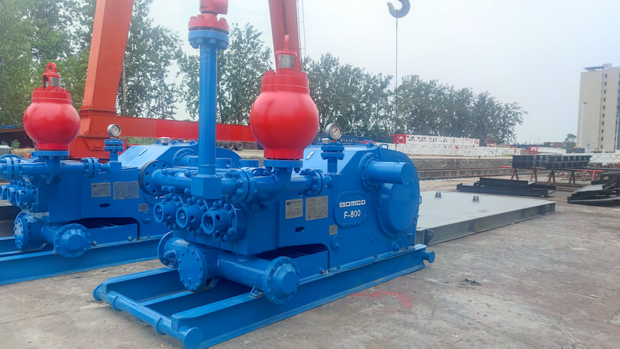
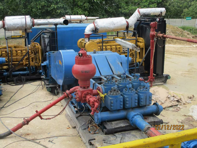
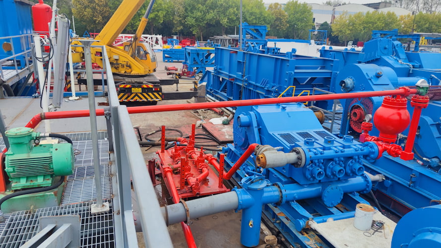
Power End:It transfers the power of the prime mover (such as an electric motor or a diesel engine) to the hydraulic end, causing the piston or plunger to move in a reciprocating manner. The main components include a pulley or a coupling (which connects the prime mover and the transmission shaft), a transmission shaft (which transmits power to the crankshaft), a crankshaft (which converts the rotational motion into the reciprocating motion of the piston or plunger), a connecting rod (which connects the crankshaft and the crosshead), and a crosshead (which moves back and forth within the slideway and transmits the motion to the piston or plunger).      Hydraulic End:It realizes the suction and discharge of mud and consists of the pump cylinder (the space where the piston or plunger moves), the piston or plunger (which changes the volume of the pump cylinder), the suction valve and the discharge valve (which control the unidirectional flow of mud), the drilling mud pump fluid end module (where the valves are installed and the mud passage is formed), and the air accumulator (installed on the discharge pipeline to reduce the pressure fluctuation of the discharged mud). Function     This is an extremely crucial pump on the drilling rig. Its core task is to circulate the drilling mud (also known as drilling fluid). The mud flows downward through the drill string, passes through the drill bit, and then returns to the surface. The mud can cool and lubricate the drill bit, carry the cuttings generated by the drill bit's breaking to the surface for removal, and maintain the pressure within the borehole to prevent blowout accidents.     The mud pump is an important part of drilling equipment. According to different classification criteria, there are various types. The following is a detailed introduction to its classification, common models, and functions: Classification by Working Principle Piston Mud Pump     Working Principle: It relies on the reciprocating motion of the piston within the pump cylinder to periodically increase and decrease the working volume of the pump cylinder, thus achieving the suction and discharge of mud. When the piston moves outward, the pressure inside the pump cylinder decreases, and the mud enters the pump cylinder through the suction valve under the action of atmospheric pressure. When the piston moves inward, the pressure inside the pump cylinder increases, and the mud is discharged through the discharge valve.     Common Models and Functions:     3NB - 1300 Type,This model is a typical triplex single action piston mud pump with a rated power of 1300 horsepower. It is suitable for medium-depth and deep well drilling operations and can provide sufficient pressure and flow rate for the mud to meet the needs of cooling the drill bit, carrying cuttings, and balancing the formation pressure. Its maximum working pressure can reach 35 MPa, and the flow rate can be adjusted according to the drilling requirements. It is widely used on both onshore and offshore drilling platforms.     F1600 Mud Pump For Drilling Rig: It belongs to a high-power piston mud pump with a rated power of 1600 horsepower. It has high reliability and stability and can adapt to complex geological conditions and large pressure fluctuations. The maximum working pressure can reach 40 MPa, and it can effectively transport high-viscosity and high-density drilling fluids. It is often used in large-scale oil drilling projects.   Plunger Mud Pump     Working Principle: Similar to the piston pump, it also changes the working volume through the reciprocating motion of the plunger in the cylinder to achieve the suction and discharge of mud. However, the plunger has a smaller diameter and a special sealing structure, enabling it to withstand higher pressures.     Common Models and Functions     PZ - 320 Type: The pressure range of this model can reach 320 MPa, meeting the requirements of ultra-high-pressure operations. The flow rate is relatively small but can be precisely adjusted. It is suitable for drilling processes that require fine operations, such as the precise injection of mud in directional drilling, ensuring that the mud is delivered to the designated location according to specific pressure and flow rate requirements.     3DP - 500 Type: It adopts a three-cylinder design and has a high flow rate and pressure output. With a relatively large rated flow rate, the maximum working pressure can reach 50 MPa. It can provide continuous and stable power support for large-scale drilling projects, especially performing well in handling drilling fluids with a high sand content and ensuring the normal operation of the mud circulation system. Classification by the Number of Cylinders Single-Cylinder Mud Pump     Working Principle: It has only one cylinder and transports mud through the reciprocating motion of a single piston or plunger.     Common Models and Functions: Due to the relatively unstable output of flow rate and pressure of the single-cylinder mud pump, it is currently less used in large-scale drilling operations. Some small single-cylinder mud pumps may be used in laboratory simulated drilling experiments or small-scale geological exploration projects to provide basic mud circulation for the experimental or exploration process. Double-Cylinder Mud Pump     Working Principle: It has two cylinders, and the two pistons or plungers work alternately, making the output of flow rate and pressure more stable compared to that of the single-cylinder pump.     Common Models and Functions: Some double-cylinder mud pumps are suitable for some shallow well drilling or small-scale drilling projects, and their pressure and flow rate can meet the basic needs of these projects. Compared with the single-cylinder pump, the double-cylinder pump has certain improvements in work efficiency and stability, but there is still a certain gap compared with mud pumps with three or more cylinders. Three-Cylinder Mud Pump     Working Principle: The three cylinders are arranged at an angle of 120°. The three pistons or plungers work alternately, making the flow rate output more uniform and the pressure fluctuation smaller.     Common Models and Functions:Common three-cylinder pump models include F-1600, F-2200, F-2500, etc. The three-cylinder pump is a reciprocating pump composed of three plungers and a crankshaft. Compared with the plunger pump, it has a higher flow rate and relatively lower pressure capacity. Commonly used three-cylinder pumps can usually provide a power output of up to 1600 to 2500 horsepower, with a maximum flow rate of 1000 to 2000 gallons per minute, and a maximum working pressure of 6000 to 7500 pounds per square inch. Three-cylinder pumps are usually suitable for deeper well depths, large-diameter boreholes, and drilling operations with larger flow rate requirements.       The selection of these pumps will depend on specific drilling requirements, including well depth, borehole diameter, working pressure, and flow rate requirements, among other factors. When selecting a pump model, it is necessary to evaluate these factors in combination and consult with the supplier according to the technical specifications and requirements of the drilling rig to determine the most suitable pump model. At the same time, it is necessary to ensure that the selected pump can cooperate well with the power system of the drilling rig to achieve stable and efficient drilling operations.   Ⅱ.Centrifugal Pump     
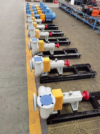
The centrifugal pump is a pump that uses the centrifugal force generated by the rotation of the impeller to transport liquids and is also widely used in drilling operations: Working Principle: The motor drives the impeller to rotate at a high speed, causing the mud to be thrown from the center of the impeller to the outer edge of the impeller under the action of centrifugal force, thereby obtaining energy and being transported out. Characteristics: It features a simple structure, easy operation, a large flow rate, and a relatively low head. It has certain requirements for the viscosity and impurity content of the mud. It has a relatively high efficiency and relatively low energy consumption. Application Scenarios: It is mainly used for the circulation, preparation, and transportation of mud, such as transporting the mud from the mud pit to the inlet of the mud pump or transporting the mud in the mud purification system.     The centrifugal mud pump is a special type of centrifugal pump, mainly used for transporting mud, ore pulp, and other media containing solid particles. The following is a detailed introduction to its classification, common models, and functions: Classification by Impeller Structure   Centrifugal Mud Pump with Closed Impeller     Structural Characteristics: The impeller has cover plates on both sides, and the blades are enclosed between the cover plates. This structure enables the impeller to effectively increase the pressure and speed of the liquid, resulting in relatively high efficiency.     Suitable Media: It is suitable for transporting mud with a relatively low concentration of solid particles and relatively small particle sizes because the flow channel of the closed impeller is relatively narrow, and overly large particles are likely to cause blockages.     Application Scenarios: It is more commonly found in scenarios such as urban sewage treatment and the transportation of ore pulp in small-scale ore dressing plants. Centrifugal Mud Pump with Open Impeller     Structural Characteristics: The impeller has no cover plates, and the blades are directly installed on the hub. The flow channel is spacious and less likely to be blocked.For example, Mission Type Open Impeller Centrifugal Sand Pump, Mission Type Magnum XP Centrifugal Sand Pump, and Mission Type Sandmaster Centrifugal Pump.     Suitable Media: It can transport mud containing large particles and a high concentration of solids, and it has strong adaptability to the media.     Application Scenarios: It is often used in working conditions such as mine slag discharge and river channel dredging, where the mud has larger particles and a higher content. Centrifugal Mud Pump with Semi-Open Impeller     Structural Characteristics: The impeller has a cover plate on only one side and combines some characteristics of both the closed and open impellers. Its efficiency is between that of the closed and open impellers, and its anti-blocking ability is also moderate.     Suitable Media: It is suitable for transporting mud containing a certain amount of particles but with relatively small particle sizes and not extremely high concentrations.     Application Scenarios: It is more frequently used in the transportation of ore pulp or coal pulp in some medium-sized ore dressing plants and coal washing plants. Classification by Pump Body Structure Single-Stage Single-Suction Centrifugal Mud Pump     Structural Characteristics: It has only one impeller, and the liquid is sucked from one side of the impeller. The structure is simple, and the manufacturing and maintenance costs are relatively low.     Performance Characteristics: The flow rate is relatively small, and the head is generally not too high, but it can meet the needs of some occasions where the requirements for flow rate and head are not particularly high.     Application Scenarios: It is often used for mud discharge in small construction sites, small sewage treatment stations, etc. Multistage Centrifugal Mud Pump     Structural Characteristics: It is composed of multiple impellers connected in series, and the liquid passes through each impeller in turn, gradually increasing the pressure.     Performance Characteristics: It can obtain a higher head and is suitable for scenarios where the mud needs to be transported over a long distance or where greater resistance needs to be overcome.     Application Scenarios: It is widely used in scenarios such as the discharge of slag from deep mines and the long-distance transportation of ore pulp in large-scale ore dressing plants. Classification by Pump Installation Method Horizontal Centrifugal Mud Pump     Structural Characteristics: The pump shaft is arranged horizontally, and the installation and maintenance are relatively convenient, with good stability.     Application Scenarios: It is the most common installation method and is suitable for most fixed installation occasions, such as the mud transportation system in factory workshops. Vertical Centrifugal Mud Pump     Structural Characteristics: The pump shaft is arranged vertically, and it occupies a small area, making it suitable for installation in places with limited space, such as small collecting wells. For example, LSB Series Vertical Sand Pump     Application Scenarios: It is often used for drainage in underground wells, dredging of small ponds, and other working conditions with limited space.     In addition, both the centrifugal sand pump and the centrifugal mud pump are special types of centrifugal pumps and play important roles in multiple fields. The following is a detailed introduction to their characteristics, working principles, application scenarios, common models, and other aspects: Ⅲ.Similarities Working Principle: Both are based on the working principle of the centrifugal pump and rely on the centrifugal force generated by the high-speed rotation of the impeller to transport the medium. Before starting, the pump casing and the suction pipe need to be filled with the medium to be transported. After starting, the prime mover drives the impeller to rotate at a high speed, and the blades drive the medium to rotate together. Under the action of centrifugal force, the medium is thrown from the center of the impeller to the outer edge of the impeller, obtaining kinetic energy and static pressure energy. After the medium enters the pump casing, due to the expansion of the cross-section of the pump casing channel, the flow rate decreases, and part of the kinetic energy is converted into static pressure energy. Finally, the medium enters the discharge pipeline from the discharge port at a relatively high pressure. At the same time, a low-pressure area is formed at the center of the impeller, and under the action of the pressure difference, the medium continuously enters the pump from the suction pipe to achieve continuous transportation. Basic Structure: Both include main components such as the impeller, the pump casing, the pump shaft, the bearings, and the sealing device. The impeller is the key component for enabling the medium to obtain energy; the pump casing is used to collect and guide the medium; the pump shaft transmits power; the bearings support the pump shaft; and the sealing device prevents the medium from leaking. Ⅳ.Differences Characteristics of the Transported Medium Centrifugal Sand Pump: It is mainly used for transporting liquids containing a large amount of sand grains or other abrasive solid particles. These solid particles have relatively large particle sizes, high hardness, and strong abrasiveness. For example, in scenarios such as river channel sand mining and ore sand transportation, the sand grain content in the medium is high, and the wear on the pump is relatively severe. Centrifugal Mud Pump: The transported medium is mud, which is a mixed liquid composed of water, clay, additives, and cuttings. The particle sizes of the solid particles are relatively small, and the viscosity of the medium is usually higher than that of the medium transported by the centrifugal sand pump. For example, the mud generated during oil drilling, construction piling, and other processes. Materials of the Flow-Through Components Centrifugal Sand Pump: In order to resist the abrasion of sand grains, the flow-through components (such as the impeller and the pump casing) usually adopt high-hardness and high-wear-resistant materials, such as high-chromium alloys. These materials have good wear resistance and impact resistance, which can extend the service life of the pump. Centrifugal Mud Pump: In addition to considering wear resistance, the flow-through components also need to consider corrosion resistance because the mud may contain various chemical substances. Generally, wear-resistant and corrosion-resistant alloy materials are used, or special treatments are carried out on the surface of ordinary materials to improve their corrosion resistance and wear resistance. Performance Characteristics Centrifugal Sand Pump: It usually needs to have a relatively high head and a large flow rate to meet the requirements of long-distance and high-concentration sand grain transportation. However, due to the abrasion of sand grains, the efficiency of the pump may decrease as the running time increases. Centrifugal Mud Pump: It pays more attention to the adaptability to high-viscosity mud and can maintain a stable flow rate and pressure when transporting high-viscosity media. Its head and flow rate vary according to specific application scenarios. Generally speaking, under the same power, due to the relatively high viscosity of the mud, its flow rate may be smaller than that of the centrifugal sand pump. Application Scenarios Centrifugal Sand Pump: It is widely used in fields such as mines, river channel sand mining, marine mining, and coal washing plants. For example, in mines, it is used to transport ore sand from the mine to the ore dressing plant; in river channel sand mining operations, it is used to extract river sand from the riverbed and transport it to the shore. Centrifugal Mud Pump: It is mainly applied in fields such as oil drilling, construction piling, sewage treatment, and mine tailings treatment. In oil drilling, it is used for circulating the mud, cooling the drill bit, and carrying the cuttings; in the construction piling process, it is used for discharging the mud in the piling holes.
    Read More

Leave A Message

Leave A Message
If you are interested in our products and want to know more details, please leave a message here, we will reply to you as soon as we can.
Submit

Home

Products

whatsApp

contact