facebook linkedin youtube whatsapp
National Unified Hotline :

+86 22 5807 5652

Email Us :

gm@geostarpe.com

#Language :

EnglishEnglish

内页banner

Search

Home

workover rig

  • What is the control system of a drilling rig?
    What is the control system of a drilling rig?
    Oct 29, 2025
    The control system of a drilling rig is the core command unit of the entire drilling equipment. It is responsible for integrating, transmitting commands, and regulating the coordinated operation of various components. Without it, the power, transmission, and execution systems of the drilling rig cannot work in an orderly manner, making it an indispensable part. Classified by control methods, it mainly includes mechanical control, pneumatic control, hydraulic control, electric control, and integrated control. Among these, pneumatic control has become the most widely used type due to its advantages of high reliability and adaptability to harsh environments, and its core consists of four major mechanisms: "air supply-command issuance-command transmission-execution". Ⅰ. Core Classifications of Control Systems 1. Mechanical Control Mechanical control is the most traditional control method. It directly transmits operating commands through mechanical components such as levers, gears, and wire ropes, featuring the simplest structure and the lowest cost. Core Principle: Operators manually operate mechanical handles to directly drive transmission components, thereby changing the actions of the execution mechanism (e.g., drawworks braking, rotary table start/stop). Applicable Scenarios: Simple control of small workover rigs and old drilling rigs, only suitable for operations with low load and low precision requirements. Limitations: Low control precision (e.g., large drilling pressure adjustment error), labor-intensive operation, inability to achieve remote or automated control, and it has gradually been replaced by other methods. 2. Pneumatic Control Pneumatic control uses compressed air as the power transmission medium. With the characteristics of "anti-pollution, resistance to high and low temperatures, and fast response", it has become the mainstream control method for onshore and offshore drilling rigs, especially suitable for control needs in harsh environments such as wellheads and mud pumps. Four Core Mechanisms and Their Functions Air Supply Mechanism: The power source of the control system, including air compressors, air reservoirs, and dryers, ensuring clean air supply and stable pressure. Command Issuance Mechanism: The command initiation end of the control system, directly operated by operators (e.g., pneumatic control handles for drawworks hoisting/lowering, buttons). When pressed or toggled, it issues control commands by changing the on/off state of the air circuit or the air pressure. Command Transmission Mechanism: The command transmission channel of the control system, including air pipelines, solenoid valves (controlling the on/off or commutation of the air circuit to realize electrical signal conversion), and pressure reducing valves (adjusting air pressure to meet the needs of different execution mechanisms). It accurately transmits commands from the command issuance mechanism to the execution mechanism. Execution Mechanism: The action execution end of the control system, which receives compressed air power and converts it into mechanical actions (e.g., cylinders, air motors, pneumatic control valves for adjusting mud pump displacement), ultimately realizing the start/stop, speed regulation, or commutation of equipment. Core Advantages Adaptability to Harsh Environments: Compressed air is non-conductive and non-flammable, immune to dust and oil/gas, less likely to freeze at low temperatures, and has a low failure rate. Fast Response Speed: The transmission delay of air pressure signals is less than 0.3 seconds, enabling rapid action in emergency working conditions (e.g., shutting down the mud pump in case of well kick) to ensure safety. Simple Structure and Easy Maintenance: No complex circuits or hydraulic oil pipelines; air pipelines and solenoid valves are easy to replace, resulting in low on-site maintenance costs. 3. Hydraulic Control Hydraulic control uses hydraulic oil as the transmission medium and drives the execution mechanism through hydraulic pressure, making it suitable for control scenarios with high load and large torque. Core Applications: Control of heavy-duty components of drilling rigs, such as blowout preventer (BOP) switching, top drive speed regulation, and braking and speed regulation of large drawworks. Advantages: Large torque transmission and high control precision. Disadvantages: Hydraulic oil is prone to contamination and requires regular filtration; its viscosity increases at low temperatures, which affects response speed; maintenance costs are higher than those of pneumatic control. 4. Electric Control Electric control uses electrical signals as the transmission medium and realizes control through motors, frequency converters, and PLC (Programmable Logic Controller). It is the core control method for intelligent drilling rigs. Core Applications: Precise parameter control (e.g., constant drilling pressure, constant speed), remote monitoring (e.g., onshore remote operation of offshore drilling rigs), and automated processes (e.g., automatic pipe connection). Advantages: High control precision, enabling data management and automation. Disadvantages: Relies on stable power supply; anti-short-circuit and anti-interference measures must be taken in humid and dusty environments; initial investment is relatively high. 5. Integrated Control Integrated control combines the advantages of two or more single control methods and is the mainstream choice for modern medium and large-sized drilling rigs (e.g., "pneumatic + hydraulic + electric control" combination). Typical Application: Pneumatic control is used for wellhead control (to adapt to oil and gas environments), hydraulic control for heavy-duty components (e.g., BOPs, to provide large thrust), and electric control for overall parameter regulation (to achieve precision and automation). The three are linked through PLC, ensuring safety and reliability while improving control precision and efficiency. Ⅱ. Core Value of the Control System Safety Guarantee: Whether it is the emergency shutdown of pneumatic control, the rapid shutdown of BOPs in hydraulic control, or the overload protection of electric control, the control system can quickly cut off risk sources in case of sudden failures (e.g., pipe sticking, well kick) to avoid equipment damage or safety accidents. Efficiency Improvement: Through precise control (e.g., constant speed regulation in electric control, top drive torque control in hydraulic control), manual operation errors are reduced, and bit wear and wellbore enlargement caused by parameter fluctuations are avoided, thereby improving drilling speed. The automated linkage of integrated control (e.g., coordination between pneumatic wellhead equipment and electric drawworks) can also shorten the time for tripping and pipe connection. Strong Adaptability: Different control methods can be adapted to different scenarios—pneumatic control for onshore remote oilfields (easy maintenance), integrated control for offshore drilling rigs (balancing safety and precision), and electric control for intelligent drilling rigs (automation needs), ensuring stable operation under various drilling conditions.  
    Read More
  • What is the transmission system of a drilling rig?
    What is the transmission system of a drilling rig?
    Oct 22, 2025
    Ⅰ. Core Components and Functions 1. Engine Core Role: As the initial power source of the transmission system, it outputs mechanical energy through fuel combustion or electric drive, and directly connects to the drive shaft via the output shaft, initiating the entire transmission chain. Applicable Scenarios: In mechanically driven or hybrid drilling rigs, it is mostly a diesel engine (e.g., V-type 12-cylinder four-stroke diesel engine); in electrically driven drilling rigs, it can be replaced by an electric motor to directly output power to the drive shaft. 2. Drive Shaft Core Role: A rigid/flexible shaft (mostly hollow steel pipe structure, with length designed according to equipment layout) connecting the engine and gearbox. It transmits the mechanical energy output by the engine to the gearbox without interruption, while adapting to slight vibrations and displacements during equipment operation (compensating for angular deviations via universal joints). Technical Features: It must have high torque-bearing capacity (usually ≥5000N・m) and fatigue resistance. Its surface is heat-treated to enhance wear resistance, preventing fracture due to long-term high-speed rotation. 3. Gearbox Core Role: Through internal gear meshing, it converts the high-speed, low-torque power input by the drive shaft into low-speed, high-torque power (e.g., when driving the drill bit) or medium-speed, medium-torque power (e.g., when driving the drawworks), meeting the working condition requirements of different equipment. Key Functions Shift Regulation: Realizes multi-stage switching of speed/torque through hydraulic or mechanical shifting (e.g., using low gear during drilling to enhance bit rock-breaking force, and high gear during tripping to improve efficiency); Reverse Transmission: Some gearboxes support reverse power output (e.g., when the drawworks lowers the drill string, reverse gears are used to achieve braking and deceleration). 4. Chain Core Role: Connects the output end of the gearbox to the bit drive mechanism (e.g., rotary table, top drive). Through the meshing of the chain and sprocket, it transmits the regulated power from the gearbox to the drill bit, driving it to rotate and break rock. Technical Advantages High torque transmission (a single chain can bear 1000-3000N・m torque), suitable for high-load operations of the drill bit, such as breaking hard rock formations; High transmission efficiency with minimal energy loss, simple structure, and low maintenance costs. Applicable Scenarios: Rotary table transmission of onshore drilling rigs and power transmission of top drive systems. 5. Belt Core Role: Through the friction between pulleys and belts, it diverts and transmits power from the gearbox to the drawworks (for tripping drill string) and mud pump for drilling rig (for circulating drilling fluid). Technical Features Flexible transmission: Can buffer power impacts, reducing wear on the gearbox; Low cost and easy replacement: Compared with chains, belts are lighter and quieter, suitable for medium and low-load scenarios. Limitations: Limited torque transmission (usually ≤1000N・m), prone to slipping under long-term high loads, requiring regular tension adjustment. 6. Hydraulic Motor Core Role: Converts the pressure energy of the hydraulic system into mechanical energy to independently drive the drill bit, drawworks, or mud pump. Technical Advantages Wide speed regulation range: Stepless speed regulation of 0-3000r/min can be achieved by adjusting hydraulic oil flow (e.g., real-time adjustment of bit speed according to formation hardness); Strong overload protection: The hydraulic system is equipped with an overflow valve, which automatically relieves pressure during overload to avoid equipment damage (e.g., protecting the bit and motor during pipe sticking); Flexible layout: No rigid connection required, enabling long-distance driving via hydraulic pipelines (e.g., mud pumps far from the power cabin in offshore drilling rigs). Typical Applications: Fine adjustment of top drives in automated drilling rigs, stable tripping of drawworks, and mud pump driving in small workover rigs. Ⅱ. Working Process of the Transmission System Power Output Stage: The engine or motor starts, outputs mechanical energy to the drive shaft, and the drive shaft stably transmits power to the gearbox by compensating for angular deviations through universal joints. Parameter Regulation Stage: The gearbox shifts according to operational requirements (e.g., drilling/tripping) to adjust speed and torque. Power Diversion Stage: High-torque power output by the gearbox is transmitted to the bit drive mechanism (rotary table or top drive) through the chain, driving the bit to rotate and break rock; Medium-torque power is transmitted to the drawworks and mud pump through the belt; The hydraulic motor independently receives power from the hydraulic system to auxiliary drive the bit, drawworks, or mud pump. Ⅲ. Key Technical Requirements and Maintenance Points 1. Technical Requirements Matching: Components must be adapted according to the "power parameter chain" (e.g., engine output torque ≥ drive shaft bearing capacity, gearbox adjustment range covers equipment requirements) to avoid overload; Reliability: In high-temperature and high-humidity environments, chains/belts must be rust-resistant, hydraulic motors must be leak-proof, and gearboxes must use temperature-resistant gear oil. 2. Maintenance Points Chains/Belts: Check tension weekly; lubricate chains and clean pulleys monthly; Gearbox: Replace gear oil every 500 hours; regularly check gear meshing clearance; Hydraulic Motor: Test hydraulic oil contamination level monthly; replace hydraulic oil filters every 1000 hours to prevent impurities from wearing internal components of the motor. The transmission system realizes full-link control of power from "output-regulation-distribution" through the collaboration of multiple components, and its performance directly determines the operational efficiency and equipment service life of the drilling rig. In modern drilling rigs, the combination of mechanical transmission and hydraulic transmission not only ensures reliability in high-load scenarios but also improves adaptability to complex working conditions, serving as the backbone for efficient operation of the drilling system.
    Read More
  • What is a truck-mounted workover rig?
    What is a truck-mounted workover rig?
    Jul 31, 2025
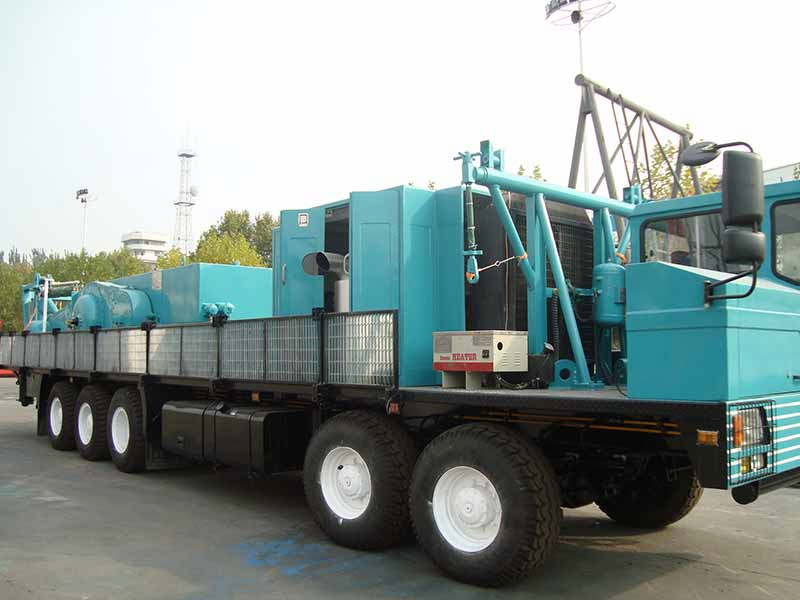
    The truck-mounted workover rig is one of the most widely used types of workover rigs. Its core feature is the integration of key components required for workover operations, such as the power system, transmission system, drawwork, and derrick, onto a heavy-duty truck chassis. Relying on the vehicle's own driving capability, it enables rapid relocation, balancing mobility and operational efficiency, and is widely applicable to conventional workover operations in onshore oilfields. The following is a detailed introduction from aspects including structural composition, core advantages, applicable scenarios, and key parameters: Ⅰ. Structural CompositionThe truck-mounted workover rig features an integrated design of "truck chassis and workover operation system", with all parts working in coordination. Heavy-Duty Truck ChassisAs the load-bearing and mobile platform of the entire equipment, it usually adopts a dedicated off-road truck chassis with multi-axle drive such as 6×4 or 8×4. Equipped with a high-horsepower engine (300-600 horsepower), a high-strength frame, and a robust suspension system, it can carry tens of tons of equipment weight and adapt to the driving needs of off-road oilfield sites. The chassis is also equipped with a high-power transmission (mostly manual or automatic) and reinforced tires (with off-road tread patterns and puncture resistance). Power SystemThe diesel engine built into the chassis serves as the main power source. Through a transfer case, power is distributed to the "driving system" and "workover operation system": when driving, it powers the wheels; during operation, the driving power is cut off to focus on providing energy for the drawwork, derrick lifting, etc.Some high-end models adopt a "dual-power system" (diesel-electric hybrid), which can switch to electric motor-driven operation to reduce noise and emissions at the well site. Core Workover Operation System 
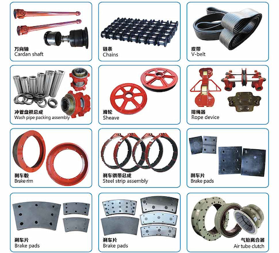
Drawwork System: Installed in the middle of the chassis, it includes components such as a drum, braking devices (main brake and auxiliary brake), and wire ropes, and is responsible for hoisting and lowering pipe strings (such as sucker rods and oil pipes). 
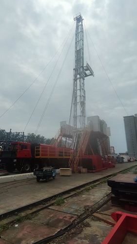
Derrick System: A foldable or telescopic derrick (usually 18-30 meters in height). During operation, it is lifted by hydraulic cylinders to provide vertical working space. A crown block is installed on the top (forming a "traveling system" with the traveling block to amplify the drawwork's pulling force). Transmission and Control System: Including a gearbox, transfer case, clutch, etc., to realize power transmission and speed adjustment; equipped with a cab (separate or integrated), through control levers and instrument panels, it controls the start/stop of the drawwork, lifting/lowering of the derrick, braking, and other actions. Auxiliary Devices: Such as blowout preventers, hydraulic outriggers (extended to stabilize the vehicle body during operation), toolboxes, and mud circulation system interfaces, which improve operational safety and convenience. Ⅱ. Core AdvantagesStrong MobilityRelying on the driving capability of the truck chassis, it does not require additional trailer traction and can directly drive on oilfield roads (with a maximum speed usually 30-60 km/h). It can quickly relocate between multiple wellheads, especially suitable for oilfields with scattered wellheads (such as small and medium-sized onshore oilfields). High Operational EfficiencyAfter arriving at the well site, the vehicle body is stabilized by hydraulic outriggers and the derrick is lifted, and the operation preparation can usually be completed within 30 minutes (much faster than the assembly time of skid-mounted or fixed workover rigs), significantly reducing non-operational time. Compact StructureAll components are integrated on the chassis with a reasonable layout and small floor space, suitable for well sites with limited space (such as cluster well groups where multiple wellheads are densely distributed). Wide AdaptabilityEquipped with chassis and drawwork of different powers, it can cover workover needs from shallow wells (<1500 meters) to medium-deep wells (1500-3000 meters), and can complete conventional operations such as pump inspection, rod replacement, fishing, and well flushing. Ⅲ. Applicable Scenarios 1.Gobi and Desert Terrain Characteristics: The surface is mainly composed of sand and gravel, with relatively flat terrain but possibly shallow pits and washboard roads, and some areas are affected by wind and sand. Adaptation Reasons: The heavy-duty off-road tires (large size and deep tread) of the truck-mounted workover rig can reduce slipping on sandy and gravelly ground, and the puncture-resistant design reduces the risk of tire damage. Multi-axle drive chassis (such as 8×4, 6×6) with uniform power distribution can handle slightly undulating terrain. The enclosed cab and air filtration system can resist the impact of wind and sand on equipment and operators. 2. Hilly and Gentle Slope Terrain Characteristics: The terrain has a certain slope (usually ≤15°), with mostly dirt roads or unpaved roads on the surface, and possibly gullies and gravel piles. Adaptation Reasons: The chassis is equipped with a high-power engine (300-600 horsepower) and a low-speed, high-torque transmission, which can provide sufficient power for climbing. The vehicle body has a lower center of gravity (compared to skid-mounted ones), and with the anti-roll stability system, it is not easy to lose balance when operating on gentle slopes. The hydraulic outriggers can adjust the telescopic length according to the slope to ensure the vehicle body is level and stable during operation. 3.Grassland and Wetland Edges Characteristics: The surface is grassland or humus soil, which may be muddy in the rainy season but does not form deep swamps, with shallow water areas (water depth ≤30cm). Adaptation Reasons: Wide-base off-road tires (with large ground contact area) can reduce pressure on the ground and lower the risk of getting stuck. Some models are equipped with a central inflation and deflation system, which can adjust tire pressure according to the softness and hardness of the ground (deflating on soft ground to increase the contact area). The chassis guard plate can prevent grassland debris (such as stones and tree roots) from scratching the engine and transmission. Limitation: It can only operate at the edge of wetlands and cannot enter deep swamps (prone to getting stuck). 4.Mountainous Unpaved Road Areas Characteristics: Narrow roads, many curves, relatively steep slopes (≤20°), with gravel or soil on the surface, and possible falling rocks or gullies. Adaptation Reasons: The short-wheelbase chassis design (for some models) can improve turning flexibility, adapting to narrow mountain roads. The reinforced suspension system (leaf springs and hydraulic shock absorbers) can buffer bumps and protect equipment components. The four-wheel drive or all-wheel drive system with differential locks can distribute power when one side of the wheels slips, ensuring passage. Limitation: Falling rocks on the road need to be cleared in advance, and when the slope exceeds 20°, auxiliary trailer traction is required. 5.Saline-Alkali Soil and Mildly Saline-Alkali Land Characteristics: The surface contains high concentrations of salt, which hardens into lumps when dry and is prone to mud when rainy, causing corrosion to metal components. Adaptation Reasons: Key chassis components (such as the frame, wheel hubs, and braking system) are coated with anti-corrosion coatings or made of stainless steel to resist salt spray erosion. Tires are made of salt- and alkali-resistant rubber materials to avoid aging and cracking caused by salt. Regular cleaning of the chassis can reduce salt accumulation and maintain equipment performance. Limitations Limited Load-Bearing Capacity: Due to the load limitation of the truck chassis, the maximum hook load is usually ≤300 tons, which cannot meet the heavy pipe string operations in deep wells (>3000 meters) or ultra-deep wells (skid-mounted or crawler-mounted workover rigs are required). High Dependence on Chassis: The reliability of the chassis directly affects the attendance rate of the entire equipment, requiring regular maintenance (such as the engine, transmission, tires, etc.). Extreme Complex Terrains Not Suitable (Requiring Dependence on Other Equipment) Deep Swamps or Muddy Areas: The surface has extremely low bearing capacity, making it easy to get stuck and unable to get out by itself. Desert Hinterland (Mobile Sand Dunes): The soft sand will cause the wheels to sink completely, requiring crawler-mounted workover rigs or desert-specific vehicles for assistance. Steep Mountainous Areas (Slope >25°): The wheeled braking system is difficult to stably park, and there is a risk of overturning during operation. Flooded Areas or Deep Water Areas (Water Depth >50cm): It will cause engine water intake and short circuits in the electrical system. Ⅳ. Key Technical Parameters (Core Indicators for Selection) Maximum Hook Load: The maximum load that the drawwork can lift (unit: kilonewton kN or ton), which is a core indicator to measure operational capability. The common range is 100-300 tons (corresponding to well depths of 1000-3000 meters). Derrick Height: Determines the maximum length of the pipe string that can be hoisted and lowered, usually 18-30 meters (can be adjusted according to the length of a single oil pipe; for example, a 9-meter single oil pipe requires a derrick height ≥12 meters). Chassis Drive Form: Such as 6×4 (6 wheels, 4 driven), 8×4 (8 wheels, 4 driven), etc. The more driven wheels, the stronger the off-road capability (adapting to muddy and gravel roads). Engine Power: The chassis engine power is usually 200-500 horsepower. The higher the power, the more sufficient the load-bearing capacity and driving power. Braking System: The performance of the main brake (hydraulic disc or band type) and auxiliary brake (eddy current or water brake) directly affects operational safety (such as braking stability when lowering the pipe string). Ⅴ. Development TrendsWith the increasing requirements of oilfields for environmental protection and intelligence, modern truck-mounted workover rigs are developing towards "energy conservation and intelligence". Adoption of electric or diesel-electric dual-power systems to reduce fuel consumption and emissions. Equipped with remote monitoring and automatic control functions (such as automatic bit feeding and brake assist systems) to improve operational safety. Enhancement of the chassis's off-road performance (such as all-wheel drive and explosion-proof tires) to adapt to more complex well site road conditions. In conclusion, relying on the characteristics of "rapid relocation and efficient operation", the truck-mounted workover rig has become the main equipment for workover operations in onshore oilfields, and is an optimal solution balancing mobility and practicality.    
    Read More
  • What is a workover rig?
    What is a workover rig?
    Jul 18, 2025
    A workover rig is a specialized equipment in the oil and gas industry used for maintenance, repair, stimulation, and fishing operations of oil and gas wells. It is a key asset for ensuring the normal production of oil and gas wells and extending the lifespan of wellbores. It can perform various downhole operations on commissioned wells, such as replacing downhole strings, repairing wellbore structures, handling downhole faults, and implementing stimulation measures like acidizing and fracturing. Ⅰ. Main Functions and Principles Main Functions 1.Workover Operations Handling stuck pipes and fallen objects: Forcibly pulling out stuck strings through the hoisting system, or using the rotary table to drive fishing tools (such as fishing spears and overshots) to retrieve downhole fallen objects (e.g., broken rods, rocks). Replacing downhole equipment: Pulling out old tubing, sucker rods, and oil well pumps, and running in new equipment to restore the production capacity of the well. Casing repair: Patching, shaping, or reinforcing damaged casings to prevent wellbore collapse. 2.Stimulation Operations Assisting in acidizing and fracturing: Running fracturing strings up and down, connecting surface fracturing equipment, and injecting fracturing fluids into the formation to enhance production. Well cleaning and paraffin removal: Removing paraffin, scaling, or sediment from well walls through circulating hot water or chemical agents to improve oil flow channels. 3.Completion Operations Assisting in cementing, running production strings, and other completion processes after the drilling of new wells. 4.Fishing Operations Retrieving broken tools and strings in the well to restore wellbore integrity. Main Principles The core working logic of a workover rig is to drive mechanisms such as the drawworks and rotary table through the power system, utilizing the lifting capacity of the derrick and the rotational capacity of the rotary table to complete operations like tripping downhole strings and handling faults: 1.Tripping strings: The drawworks winds the wire rope, which, through the crown block sheave (usually 3-5 sheaves) composed of the crown block and traveling block, converts power into lifting force to suspend and hoist tubing, sucker rods, etc. When lowering, the speed is controlled by the braking system to ensure stable operation. 2.Rotational operations: The rotary table drives downhole drilling tools or casings to rotate through gear transmission, enabling operations such as casing milling and grinding (e.g., back-off and cutting when handling stuck pipes). 3.Auxiliary operations: Adjusting the derrick angle and extending outriggers through the hydraulic system to ensure the equipment is aligned with the wellhead; safety devices like blowout preventers (BOPs) control the risk of well kicks and blowouts during operations. Ⅱ. Basic Components A workover rig typically consists of the following core components: Substructure Mostly specialized heavy-duty truck substructures or crawler substructures, providing mobility and operational support.The substructure must have sufficient load-bearing capacity and stability; some models are equipped with hydraulic outriggers, which are deployed during operations to distribute weight and prevent tipping. Derrick Used to suspend and hoist downhole tools and strings, with a certain load-bearing capacity and height. 1.Main structure (derrick frame) Material: Mostly high-strength low-alloy steel (e.g., Q345, Q460), formed into a truss structure through welding or bolting, balancing light weight and high strength. Structure type: Mainly "quadrangular pyramid" or "portal" trusses, composed of columns, cross braces, and diagonal braces to form a stable spatial framework. Columns are the main load-bearing components, while cross braces and diagonal braces enhance overall rigidity to prevent deformation. 2.Crown block platform  Located at the top of the derrick, used to install the crown block and equipped with anti-collision devices, guardrails, and other safety facilities. The crown block consists of multiple sheaves, connected to the drawworks and traveling block via wire ropes to transmit force and change direction, serving as a key node in the hoisting system. 3.Derrick Substructure A supporting structure connecting the derrick to the workover rig substructure (or ground), used to raise the height of the derrick base and reserve space for wellhead operations (e.g., BOP installation, string connection). Some bases are telescopic or foldable to reduce height during transportation and expand to enhance stability during operations. 4.Guy line system For self-supporting derricks (non-tower type), multiple sets of guy lines (steel cables) are required to anchor the top of the derrick to the ground, balancing horizontal loads on the derrick to prevent tipping. One end of the guy line is connected to the lifting lug at the top of the derrick, and the other end is fixed to the ground anchor. The tension is adjusted via turnbuckles to ensure the derrick is vertically stable. 5.Erecting mechanism Used to raise and lower the derrick, usually driven by hydraulic cylinders, drawworks wire ropes, or chains. The lifting process requires strict control of speed and angle to avoid excessive stress-induced deformation of the derrick. 6.Safety accessories Crown block collision preventer: Automatically triggers drawworks braking when the traveling block rises close to the crown block, preventing "crown block collision" accidents. Ladders and guardrails: Safety channels for personnel to climb the derrick and operate on the monkey board, ensuring safety during high-altitude operations. Anti-slip pedals: Installed on the surfaces of platforms such as the monkey board and crown block platform to prevent personnel from slipping. Ⅲ. Classification According to mobility and operation scenarios, workover rigs can be classified into: Truck-mounted workover rigs: The most common type, mounted on heavy-duty truck substructures, with strong mobility, suitable for conventional onshore well operations. Crawler-mounted workover rigs: Adopting crawler substructures with low ground pressure, suitable for complex terrains such as muddy areas and mountainous regions. Skid-mounted workover rigs: Equipment disassembled into multiple skids, transported by trailers, and assembled on-site, suitable for fixed well sites or large-scale workover operations. Offshore workover rigs: Installed on drilling platforms or workover vessels, adapted to offshore oil and gas well operations, with corrosion resistance and wind-wave resistance. According to power and load capacity: Small workover rigs: Rated load < 300kN, used for simple maintenance of shallow wells (< 1000 meters), water wells, or low-yield oil wells. Medium workover rigs: Rated load 300-500kN, suitable for conventional workover operations of medium-deep wells (1000-3000 meters). Large workover rigs: Rated load > 500kN, used for deep wells (> 3000 meters) or complex wells (e.g., horizontal wells, high-pressure wells), capable of handling high-load and high-risk operations. Ⅳ. Industry Standards The design, manufacturing, and use of workover rigs must comply with relevant industry standards, such as China's SY/T (Oil and Gas Industry Standards) and the American Petroleum Institute (API) standards, to ensure their safety, reliability, and operational efficiency. In oil and gas field development, workover rigs complement drilling rigs: drilling rigs are responsible for "drilling wells," while workover rigs are responsible for "maintaining wells," jointly ensuring the efficient extraction of oil and gas resources.
    Read More

Leave A Message

Leave A Message
If you are interested in our products and want to know more details, please leave a message here, we will reply to you as soon as we can.
Submit

Home

Products

whatsApp

contact