What is the difference between Kelly Drive and top drive?
Feb 21, 2025
The main differences between the kelly drive and the top drive are as follows:
Ⅰ. Main differences
Structural Location:The kelly drive device is mainly composed of a rotary table, a swivel, a kelly, etc. The rotary table is on the drill floor and cooperates with the kelly through a kelly bushing. The top drive drilling system is generally installed at the top of the derrick and includes components such as the swivel-drilling motor assembly, the motor support/guide trolley assembly, and the drill pipe make-up and break-out assembly.
Driving Method:The power of the kelly drive device comes from the ground rotary table. It drives the kelly to rotate through the kelly bushing, and then drives the drill string and the drill bit. The top drive is directly driven by the drilling motor installed at the top of the derrick to rotate the top of the drill pipe.
Drilling Mode:The kelly drive device adopts single joint drilling. After drilling a length of one kelly (about 9 meters), a joint connection operation is required. The top drive adopts stand drilling. A stand is usually composed of three drill pipes, with a length of approximately 28 meters
Well Control Operation:In the case of well kicks and other situations during tripping operations with the kelly drive device, the kelly needs to be lifted out first, and then blowout preventers and other equipment are connected to establish a well control circulation channel. The top drive is generally equipped with two sets of internal blowout preventers, which can connect the drill string quickly, close the annular blowout preventer, and establish the mud circulation within a short time.
Automation Degree:The kelly drive device has a relatively low degree of automation, and more manual operations are required for operations such as connecting drill pipe joints. The top drive has a high degree of automation, and many operations can be automated or remotely controlled.
The following is a detailed introduction to these two types of products to help you find more suitable equipment:
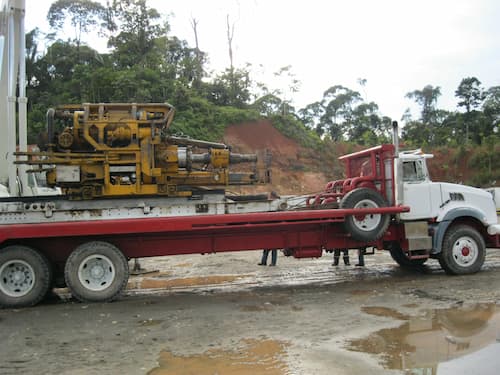
Ⅱ. Kelly Drive
The kelly drive device usually refers to the rotary table drive device because in drilling operations, the rotary table generally drives the kelly to rotate. The following is an introduction to the kelly drive device.
Structural Composition
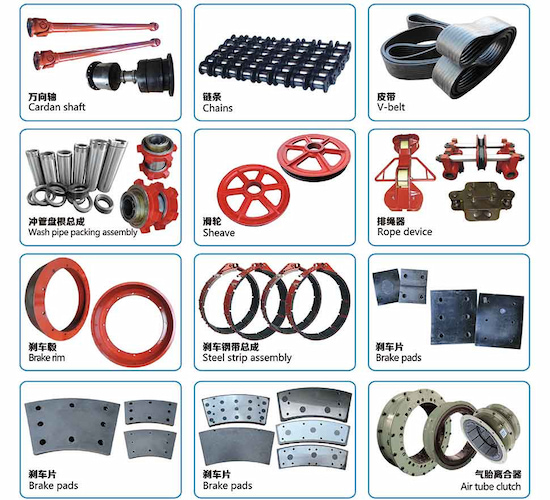
Transmission Part: It mainly includes components such as the coupling, the input shaft of the chain box, the chain, and the sprocket. Its function is to introduce and transmit power. For example, in the ZP375 rotary table drive device, the power of the motor is transmitted to the rotary table through these components, and then drives the kelly.
Support Part: It includes the rotary table beam, the chain box, etc., which are responsible for the positioning and installation of the rotary table, the chain box, the transmission parts, etc., providing stable support for the entire drive device.
Control Part: It mainly includes components such as the disc brake, the gas circuit and electrical circuit valves, and the pipelines, which are used to control the operation and speed regulation of the rotary table, and realize the control of the rotation speed and start/stop of the kelly.
Working Principle:Taking the ZP275 rotary table drive device as an example, this device uses an AC variable-frequency motor as the power source and adopts a modular structure with chain transmission. After the motor is started, the generated power is transmitted to the input shaft of the chain box through the coupling, and then through the transmission of the chain and the sprocket, the power is transmitted to the rotary table. When the rotary table rotates, the kelly that cooperates with the rotary table bushing rotates accordingly, and then transmits the torque to the drill pipe, driving the drill bit to carry out the drilling operation.
Application Scenarios:It is widely used in traditional rotary table drilling operations. Whether it is onshore drilling or offshore drilling, as long as the drilling rig uses the rotary table to drive the kelly for drilling, a kelly drive device is required. For example, in some shallow well drilling and drilling operations under ordinary geological conditions, the kelly drive device can meet the basic drilling requirements.
Ⅲ. Advantages of Kelly Drive
The kelly drive device has the following advantages:
Simple and Reliable Structure
Simple Composition: It is mainly composed of basic components such as the rotary table, the kelly, and the swivel. There are no complex intermediate transmission links or too many auxiliary devices, and the structure is relatively simple, making it easy to manufacture, install, and maintain.
High Stability: This simple structure makes the connection and cooperation between various components relatively direct. During the drilling process, it can stably transmit power and torque, reducing the possible failure points caused by a complex structure, and has high working reliability.
Easy to Operate
Familiar Operation Process: Drilling workers are very familiar with its operation process and can master it proficiently after simple training. For example, when connecting drill pipe joints, only a conventional threaded connection operation between the kelly and the drill pipe is required, without the need for complex equipment and technology.
Direct Control Method: By controlling the rotation speed and direction of the rotary table, the rotation of the kelly and the drill string can be directly controlled, and then the drilling speed and direction of the drill bit can be controlled. The control method is intuitive and simple, facilitating operators to make timely adjustments according to the actual drilling situation.
Good Cost-effectiveness
Low Equipment Cost: Compared with some advanced top drives, etc., the equipment procurement cost of the kelly drive device is relatively low. There is no need to purchase high-end equipment such as expensive top drive systems, which has a great cost advantage for some drilling projects with limited budgets.
Low Maintenance Cost: Due to its simple structure, its maintenance work is relatively easy, and the required maintenance equipment and tools are also common, resulting in a low maintenance cost. Daily maintenance mainly involves inspecting, lubricating, and replacing vulnerable parts of the rotary table, the kelly, and other components, without the need for professional high-tech personnel and special maintenance facilities.
Ⅳ. Disadvantages of Kelly Drive
The kelly drive device has the following disadvantages:
In Terms of Drilling Efficiency
Frequent Joint Connection: The length of the kelly is limited, usually about 9 meters. A joint connection operation is required every time a certain distance is drilled, which will consume a lot of time and reduce the overall drilling efficiency.
Slow Tripping Speed: During the tripping process, the kelly needs to be removed from or installed at the wellhead, and the operation is relatively complicated, resulting in a slow tripping speed. Especially when dealing with complex situations such as stuck pipes, the drill string cannot be connected quickly for processing.
In Terms of Operation Safety
High Labor Intensity: Operations such as connecting drill pipe joints require a lot of physical labor by workers. Workers need to operate frequently at the wellhead, and the labor intensity is relatively high. Moreover, working in such a high-intensity state for a long time is likely to cause fatigue, increasing the risk of operational errors.
High Safety Risk: Since a large number of operations by workers are required near the wellhead, such as connecting the kelly and operating the rotary table, there are many dangerous areas around the wellhead. For example, high-pressure mud may spray out, and the drill string may rotate accidentally, which poses a great threat to the safety of operators.
In Terms of Power Transmission and Control
Torque Loss: The power is transmitted from the rotary table to the kelly, and then to the drill string and the drill bit. There are multiple connection parts in the middle, resulting in a certain torque loss and reducing the power transmission efficiency. Especially in deep wells or situations with high torque requirements, this torque loss may be more obvious, affecting the rock-breaking effect of the drill bit.
Low Control Precision: The control of the rotation speed and torque of the kelly drive device is relatively rough, and it is difficult to achieve precise control. In some situations where precise control of drilling parameters is required, such as directional drilling and horizontal drilling, the kelly drive device may not be able to meet the requirements, making it difficult to control the wellbore trajectory.
Equipment Wear
Severe Drill Pipe Wear: The drill pipe and the drill bit rotate together. The deeper the drilling, the more drill pipes are used, and the greater the weight driven by the rotary table. The wear of the drill pipe also increases exponentially.
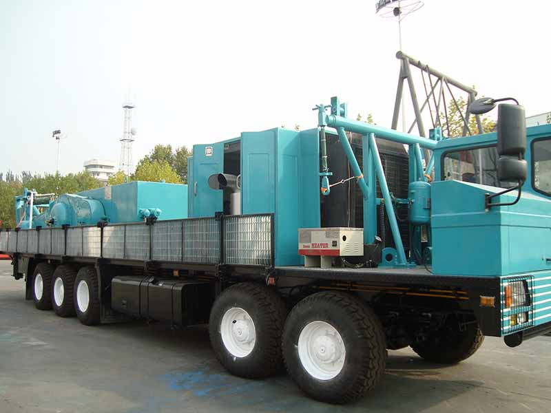
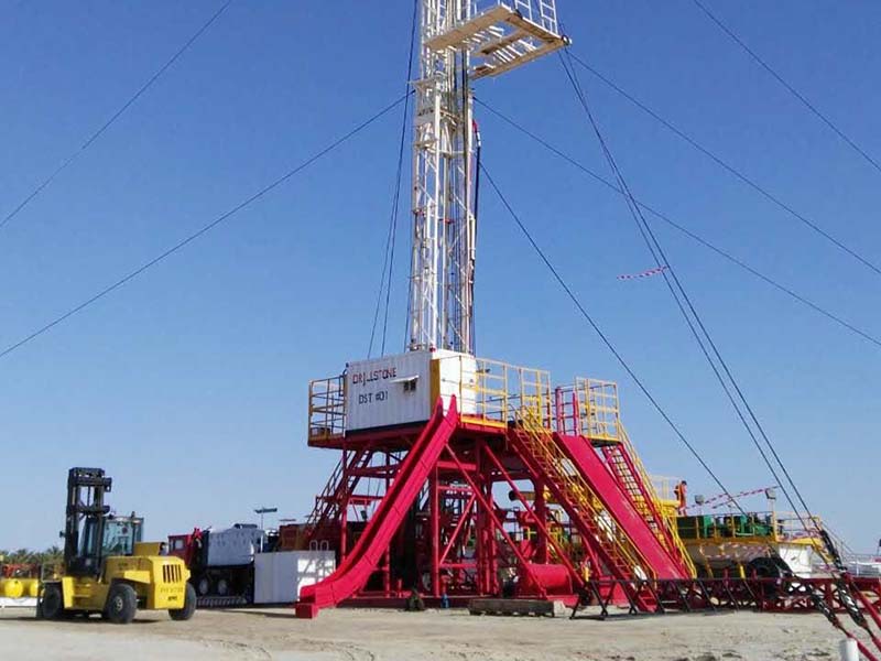
Ⅴ. Top Drive Drilling System
The top drive drilling system, abbreviated as the “top drive”, is a new type of drilling equipment that emerged in the 1980s. It is known as the third revolution in the field of drilling equipment and is one of the three major technical achievements of modern drilling equipment.
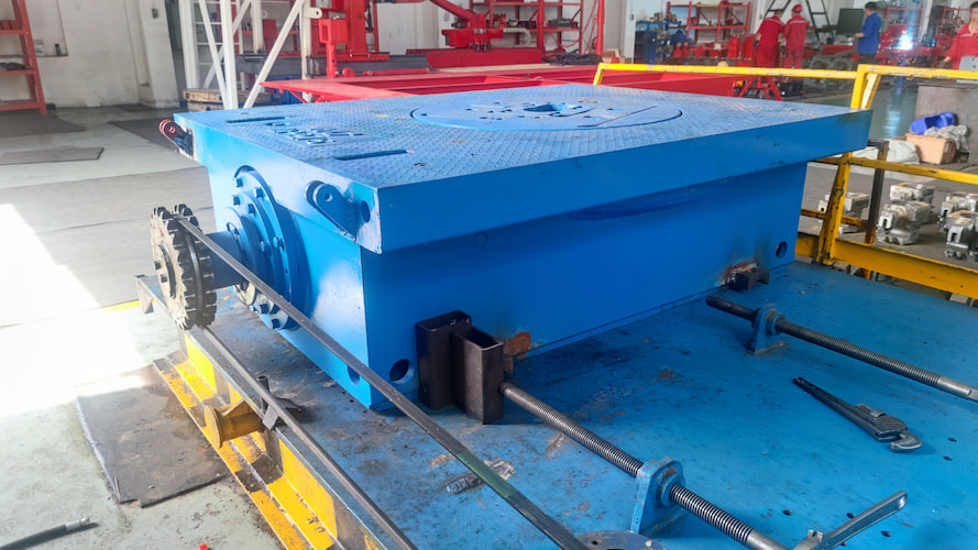
Structural Composition
Swivel-Drilling Motor Assembly: It is the core component, which combines the swivel and the drilling motor to provide the rotation power and the mud passage for the drill string.
Motor Support/Guide Trolley Assembly: It moves along the guide rail and can serve as the support beam for the motor, guiding the up and down movement of the top drive.
Drill Pipe Make-up and Break-out Assembly: It includes components such as the torque wrench, the internal blowout preventer and the starter, the elevator link connector and the torque limiter, the elevator link tilting device, and the swivel head, etc., to realize the make-up and break-out operations of the drill pipe.
Balance System: It prevents the thread damage during the make-up and break-out of the joints and helps the pin joint to pop out from the box joint during the break-out operation.
Cooling System: Generally, the air cooling method is adopted to dissipate heat for components such as the drilling motor.
Control System of the Top Drive Drilling Device: It realizes various operation controls of the top drive to ensure the safe and efficient operation of the operation
Working PrincipleThe motor of the top drive transmits the power to the main shaft through the reduction gearbox. The main shaft drives the swivel to rotate, and then makes the drill pipe connected to the swivel generate a rotational movement, realizing the breaking of the formation by the drill bit. At the same time, under the action of the mud pump, the mud enters the inside of the drill pipe through the central passage of the swivel, and then sprays out from the nozzles of the drill bit, carrying the cuttings back to the surface, completing the mud circulation process, playing the roles of cooling the drill bit, carrying the cuttings, and stabilizing the wellbore.
As an important piece of equipment in the field of oil drilling, the top drive has many characteristics and advantages, which are mainly reflected in the following aspects:
In Terms of Drilling Efficiency
Reducing the Time for Connecting Drill Pipe Joints: Traditional drilling uses the kelly drive, and the drill pipes need to be connected one by one. However, the top drive can adopt stand drilling. Generally, a stand is composed of three drill pipes, which greatly reduces the frequency and time of connecting drill pipe joints. In deep well and ultra-deep well drilling, it can significantly shorten the drilling cycle.
Continuous Mud Circulation: During the operation of connecting drill pipe joints or tripping, the top drive can realize the continuous circulation of the mud. There is no need to interrupt the circulation frequently as in the traditional way, which helps to maintain the stability of the wellbore, reduce the occurrence of downhole complex situations, and also saves the time consumed for restoring the circulation.
Rapid Directional Drilling: In directional drilling operations, the top drive can adjust the direction of the bottom hole assembly more quickly and accurately. Through the cooperation with the downhole power drilling tool and the measurement while drilling system, it can efficiently complete operations such as directional deflecting and azimuth changing, improving the efficiency and accuracy of directional drilling.
In Terms of Operation Safety
Reducing the Risk of Manual Operation: It has a high degree of automation. Many dangerous operations that originally required manual operation, such as connecting and disassembling drill pipes at the wellhead, can be completed by the automation system of the top drive, reducing the working time and frequency of workers in high-pressure and high-risk environments, and reducing the labor intensity and safety risk.
Equipped with Safety Protection Devices: It is equipped with a variety of safety protection functions, such as torque overload protection, overcurrent protection, and the braking system, etc. When abnormal situations occur during the drilling process, such as the torque suddenly increasing and exceeding the set value, the protection device will be activated immediately to stop the operation of the equipment, avoiding accidents such as the drill pipe being twisted off and the equipment being damaged, and ensuring the safety of personnel and equipment.
Convenient for Well Control Operation: In case of emergency situations such as well kicks and blowouts, the top drive can quickly realize the connection between the drill pipe and the blowout preventer, rapidly establish the well control circulation channel, and timely control the pressure in the well, effectively preventing the expansion of the accident and improving the reliability and timeliness of well control.
In Terms of Drilling Quality
Precise Control of Drilling Parameters: It can precisely control the rotation speed, torque, and weight on bit of the drill pipe. Operators can adjust these parameters in real time according to different formation conditions and drilling process requirements, so that the drill bit always remains in the best working state, which helps to improve the drilling quality and reduce the occurrence of problems such as well deviation and well collapse.
Realizing Back Reaming and Tripping Reaming: During the drilling process, if situations such as unstable wellbore and hole shrinkage are encountered, the top drive can conveniently carry out back reaming or tripping reaming operations. By rotating the drill pipe and moving it up and down, it can trim the wellbore, remove the cuttings bed and obstacles in the well, ensure the regularity and smoothness of the wellbore, and create good conditions for subsequent operations such as cementing and logging.
In Terms of Economic Benefits
Reduction of Comprehensive Costs: Although the initial purchase cost of the top drive is relatively high, due to its ability to improve drilling efficiency, reduce downhole accidents, and lower labor costs and maintenance costs, etc., from the perspective of the entire life cycle of the drilling project, it can significantly reduce the comprehensive cost and improve the economic benefits.
Increase of Oil and Gas Recovery Rate: Through efficient and high-quality drilling operations, the top drive can better realize the exploration and development of oil and gas reservoirs, increase the production and recovery rate of oil and gas wells, and provide a strong guarantee for the long-term stable production and economic benefit improvement of oil and gas fields.
Read More


 Language :
 English
 Русский
 عربي
عربي
 GET A QUOTE


 IPv6 network supported