facebook linkedin youtube whatsapp
National Unified Hotline :

+86 22 5807 5652

Email Us :

gm@geostarpe.com

#Language :

EnglishEnglish

内页banner

Search

Home

drill string

  • What is a drill string stabilizer?
    What is a drill string stabilizer?
    Aug 08, 2025
    The Drill String Stabilizer is a critical tool installed on the drill string in oil and gas drilling, geological exploration, and other engineering projects. Its primary functions include stabilizing the drill string, controlling wellbore trajectory, reducing drill string vibration and wear, and ensuring efficient and safe drilling operations. Below is a detailed introduction: I. Core Functions Stabilizing the drill string and preventing deviationThrough contact with the wellbore wall, the stabilizer provides radial support for the drill string, reducing lateral oscillation of the drill string during rotation and drilling. This prevents the wellbore from deviating from the designed trajectory (e.g., trajectory control in directional or horizontal wells). Controlling wellbore diameterThe outer diameter of the stabilizer is close to that of the drill bit, allowing it to scrape excess rock or mud cake from the wellbore wall. This ensures a regular wellbore shape, prevents wellbore enlargement or shrinkage, and creates favorable conditions for subsequent cementing and completion operations. Reducing drill string wear and fatigueIt minimizes friction between the drill string and the wellbore wall, reduces bending and vibration of drill pipes and drill collars, extends the service life of drill tools, and lowers the risk of accidents such as drill string breakage and sticking. Optimizing hydraulic performanceSome stabilizers are designed with diversion grooves or water eyes, which improve the flow path of drilling fluid, enhancing sand-carrying capacity and the efficiency of bit cooling. II. Main Classifications and Structural Features Drill string stabilizers can be categorized based on structural design, application scenarios, and stabilization principles: Classified by Structural Form Integral Stabilizer Structure: Forged from a single piece of steel (e.g., alloy steel) and machined, with ribs integrated into the main body (no welded or assembled components). Features: High strength and impact resistance, suitable for deep wells, hard formations, or high-rotational-speed drilling scenarios. Application: Deep well drilling, hard rock formations, and high-build-rate sections of directional wells. Insert-type Stabilizer Structure: Hard alloy inserts (e.g., tungsten carbide teeth) or polycrystalline diamond compact (PDC) inserts are embedded in the ribs of the main body. Features: Exceptional wear resistance, effectively handling abrasive formations (e.g., sandstone, conglomerate) and extending service life. Application: Abrasive formations and horizontal well sections (requiring long-term contact with the wellbore wall). Replaceable Sleeve Stabilizer Structure: The main body serves as a base, with a detachable wear-resistant alloy sleeve for stabilization. Worn sleeves can be replaced without discarding the entire body. Features: Cost-effective, reducing maintenance costs, suitable for medium to low abrasive formations. Application: Conventional vertical wells and secondary/multiple use requirements in medium-deep wells. Spiral Stabilizer Structure: Ribs are distributed in a spiral pattern, minimizing contact area with the wellbore wall and ensuring smoother fluid passage. Features: Reduces drilling fluid flow resistance and pressure loss, while providing both stabilization and diversion functions. Application: High-displacement drilling and horizontal sections (reducing cuttings bed accumulation). Classified by Installation Position Near-bit Stabilizer: Installed closest to the drill bit (typically 0.5–3 meters above the bit), directly controlling bit deviation and serving as the core tool for trajectory control. Middle Stabilizer: Installed in the middle of the drill string to assist in stabilizing the string and reducing overall bending deformation. Top Stabilizer: Located near the wellhead or rotary table, primarily preventing oscillation of the drill string near the wellhead. III. Structural Composition Drill string stabilizers typically consist of the following components: Main Body: A cylindrical metal structure, usually made of high-strength alloy steel, with wear and impact resistance. Stabilizing Ribs (Blades): Protruding structures evenly distributed around the circumference of the main body (commonly 3–6 ribs). These are the core contact points with the wellbore wall, with rib shape and quantity designed based on drilling requirements. Connection Threads: Equipped with drill pipe threads (e.g., API standard threads) at both ends for connection to the drill string (drill collars, drill pipes). Diversion Grooves: Grooves between the blades for drilling fluid circulation. Some designs optimize groove geometry to reduce pressure loss. IV. Key Technical Parameters Outer Diameter: Matches the wellbore size, typically 3–5mm smaller than the wellbore diameter (e.g., a 215.9mm wellbore uses a 210mm stabilizer), ensuring stabilization while avoiding sticking risks. Number of Ribs: Commonly 3, 4, or 6 ribs. More ribs improve stability but may increase drilling fluid flow resistance. Length: Designed based on well section requirements. Near-bit stabilizers are usually shorter (0.5–1.5 meters), while middle stabilizers can be longer (1–3 meters). Material: Main Body: Mostly high-strength alloy steels such as 4145H or 4140H, tempered to provide good toughness and fatigue resistance. Wear-resistant Components: Tungsten carbide (WC-Co), PDC inserts, ceramic coatings, etc., to enhance wear resistance. Maximum Operating Pressure/Temperature: Designed to withstand high-temperature and high-pressure environments in deep wells. Conventional products tolerate temperatures ≥150°C and pressures ≥30MPa. V. Application Scenarios and Selection Principles Formation Characteristics Soft Formations: Prioritize spiral or integral stabilizers to minimize formation disturbance. Hard/Abrasive Formations: Insert-type stabilizers are mandatory to prevent rapid wear. Well Type Requirements Vertical Wells: Focus on deviation control, selecting high-stability integral or 4-rib stabilizers. Directional/Horizontal Wells: Near-bit stabilizers require high-precision design, paired with spiral structures to reduce cuttings accumulation. Drilling Parameters High rotational speed (≥150rpm) drilling requires integral stabilizers with strong fatigue resistance.High-displacement drilling prioritizes spiral structures. VI. Application Considerations Selection Adaptation: Choose the appropriate stabilizer type based on formation hardness, well type (vertical/directional/horizontal), and drilling fluid properties. Installation Position: Typically installed above the bit near the drill collar, or spaced according to drill string design to form a "full-hole drill string" structure. Maintenance Inspection: Regularly check rib wear and thread integrity to avoid wellbore deviation or drill string damage due to stabilizer failure. Coordination with Other Tools: Work synergistically with bits, drill collars, shock absorbers, etc., to optimize overall stability of the drill string assembly. VII. Usage and Maintenance Guidelines Pre-run Inspection Check rib wear (replace if wear exceeds design limits). Inspect the main body for cracks, deformation, or thread damage. Ensure inserts are not loose or missing, and spiral channels are unobstructed. In-use Monitoring Real-time monitoring of torque and weight-on-bit fluctuations; anomalies may indicate stabilizer failure. Regularly evaluate wellbore trajectory using Measurement While Drilling (MWD) data to verify stabilizer effectiveness. Maintenance Clean residual drilling fluid after use and inspect wear on critical components. Replace worn inserts for insert-type stabilizers and timely replace sleeves for replaceable sleeve stabilizers.   The drill string stabilizer achieves the core goal of "stable drill string – regular wellbore – efficient drilling" through three synergistic functions: rigid support to suppress drill string oscillation, trajectory constraints to control wellbore direction, and hydraulic optimization to enhance sand-carrying and cooling efficiency. Its performance directly impacts drilling safety, wellbore quality, and operational costs, making it an indispensable tool in complex well drilling (e.g., shale gas horizontal wells, deep wells).
    Read More
  • What is the hoisting system in oil drilling?
    What is the hoisting system in oil drilling?
    Apr 02, 2025
    The hoisting system in oil drilling is a crucial component of oil drilling equipment, mainly used for tripping drill strings and casings, as well as suspending drill strings during drilling operations. The following are some of the main equipment in this system: 
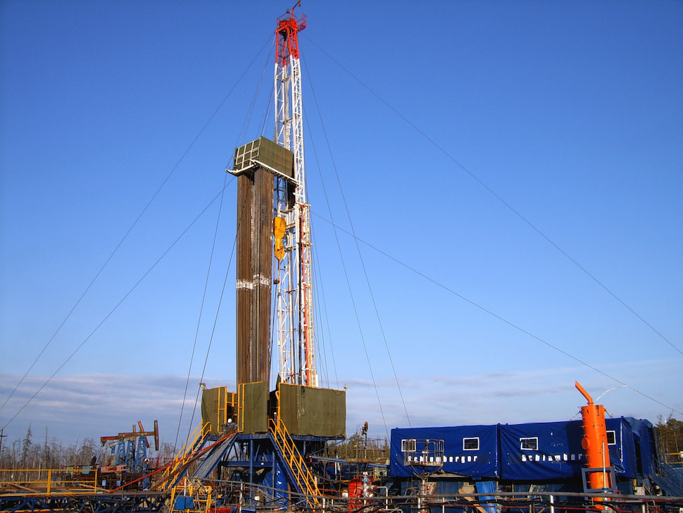
Ⅰ. DerrickStructural Features: The derrick is a large-scale steel structure, usually including types such as the tower-shaped derrick, A-shaped derrick, and mast derrick. The tower-shaped derrick has an overall tower-like structure, with high stability and load-bearing capacity, capable of withstanding large loads. However, it is large in size, heavy in weight, and relatively complex in disassembly, assembly, and transportation. The A-shaped derrick is composed of two inclined brackets and a top crossbeam, resembling the letter "A" in shape. It has a compact structure, is convenient for disassembly and assembly, and is widely applied. The mast derrick is relatively low and has a small footprint, suitable for places with limited space.Function: The derrick provides support and fixation for the entire hoisting system. Through its steel structure framework, it bears the weights of equipment such as the crown block, traveling block, and drill string, as well as various tensile forces and pressures generated during the hoisting process. It enables the drill string to be raised and lowered vertically, and provides installation positions for hoisting equipment and tools such as the crown block, traveling block, rotary swivel, (top drive) power tongs, and elevator. It also ensures that operators have sufficient space for drilling operations. Ⅱ. Crown Block Structural Composition: Installed at the top of the derrick, it is a fixed sheave block composed of multiple sheaves.The crown block sheaves are usually made of high-quality steel, with high wear resistance and strength to withstand the huge tensile forces generated by frequent hoisting and lowering operations.Function: It changes the direction of the wire rope, transmits the pulling force of the drawworks to the traveling block, and realizes the hoisting and lowering of the drill string. Through the combination of multiple sheaves, it can effectively distribute the pulling force, reduce the load borne by a single sheave, and improve the reliability and safety of the system. Ⅲ. Traveling BlockStructural Features: Connected to the crown block by a wire rope, it is a movable sheave block, usually composed of multiple sheaves, which cooperates with the sheave block of the crown block through the wire rope to form a labor-saving hoisting system. The number and size of the sheaves are determined according to the load-bearing capacity of the traveling block and the requirements of the drilling operation. The lower part of the traveling block is connected to the drill string through the traveling block hook. Under the action of the hoisting system, it drives the drill string to move up and down. The structural design of the traveling block should ensure its flexibility and stability during movement, and it should be able to withstand the weight of the drill string and the impact force during the hoisting process.Function: Driven by the drawworks, it moves the drill string up and down through the pulling of the wire rope. Since the traveling block is a movable sheave block, according to the principle of labor-saving of the sheave block, it can amplify the pulling force of the drawworks, enabling the hoisting of heavier drill strings. Ⅳ. HookStructural Composition: The hook is connected below the traveling block, suspending the drill string through the hook body, and forms a hoisting system together with the traveling block, crown block, and drawworks. The hook has a rotatable hook body and a safety locking device.Function: Its working principle is relatively simple. It mainly uses its own structural features and connection devices to transmit the pulling force of the traveling block to the drill string, facilitating the connection and separation with the joint of the drill string, and preventing the drill string from accidentally falling off during the hoisting process. The rotating function of the hook body allows the drill string to rotate as needed during the hoisting and lowering process. For example, when connecting or disassembling drill pipes, it enables the threads of the drill pipes to be accurately aligned. The safety locking device of the hook prevents the hook body from accidentally opening after the drill string is suspended, ensuring that the drill string will not fall off and guaranteeing the safety of the operation. The load-bearing capacity of the hook varies according to the depth of the well and the weight of the drill string, generally ranging from several dozen tons to several hundred tons. Ⅴ. DrawworksThe drilling drawworks is not only the main equipment of the hoisting system but also the core part of the entire drilling and workover rig, and it is one of the three major working units of the drilling and workover rig. A classic three-axis electric-driven drilling rig.Structural Features: As the power equipment of the hoisting system and the power source, it is usually driven by an electric motor or a diesel engine. The drawworks contains components such as a transmission device, a drum, and a braking system.Function: It controls the lifting speed and position of the traveling block and the drill string by winding and unwinding the wire rope. The transmission device can transmit power to the drum at different rotation speeds and torques according to different operation requirements. When the drill string needs to be hoisted, the drum rotates forward and winds the wire rope, thus pulling the traveling block and the connected drill string upward; when lowering the drill string, the drum rotates in reverse and releases the wire rope, and the drill string slowly descends under its own gravity. The braking system uses components such as brake pads or brake discs to quickly stop the rotation of the drum when necessary, making the drill string stop at the specified position and achieving the hovering function, ensuring the safety and precise control of the operation. Ⅵ. Wire RopeStructural Features: Made of high-strength and corrosion-resistant steel, it has high breaking tensile force and good flexibility. Generally, it is twisted by multiple strands of steel wires, and the outer layer may also have a protective layer to improve its wear resistance and corrosion resistance. In order to ensure the service life and safety of the wire rope, it is necessary to regularly inspect, lubricate, and replace it. When selecting a wire rope, an appropriate one should be determined according to factors such as the depth of the well and the load.Function: It connects the crown block, traveling block, and drawworks, transmits the pulling force, and suspends the drill string. During the drilling process, the wire rope needs to bear a huge pulling force, so its quality and performance directly affect the safety and reliability of the hoisting system. The wire rope bypasses multiple sheaves of the crown block and traveling block to form a multi-strand rope system. According to the principle of labor-saving of the sheave block, in this way, the drawworks only needs to provide a pulling force smaller than the gravity of the drill string to achieve the hoisting of the drill string. For example, a crown block and traveling block system composed of multiple sheaves can amplify the pulling force of the drawworks several times, enabling the hoisting of drill strings weighing dozens of tons or even hundreds of tons. At the same time, the sheave block can also change the direction of the force, allowing the drawworks to be operated in a more convenient position while the drill string can be raised and lowered vertically. In addition, the oil drilling hoisting system may also include some auxiliary equipment, such as the anti-collision device for preventing the traveling block from rising too high and colliding with the crown block, and the dead rope anchor for fixing one end of the wire rope. These devices work together to ensure that the oil drilling hoisting system can operate safely and efficiently, and complete the operations such as tripping drill strings and casings during the oil drilling process.
    Read More

Leave A Message

Leave A Message
If you are interested in our products and want to know more details, please leave a message here, we will reply to you as soon as we can.
Submit

Home

Products

whatsApp

contact