How to Choose the Right Centrifugal Sand Pump for High-Viscosity Drilling Fluid?
Apr 01, 2026
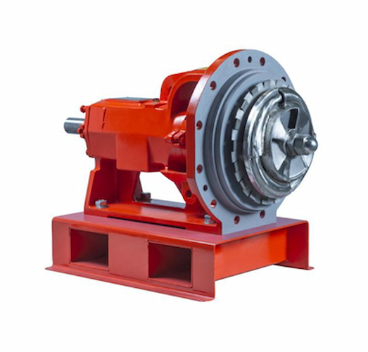
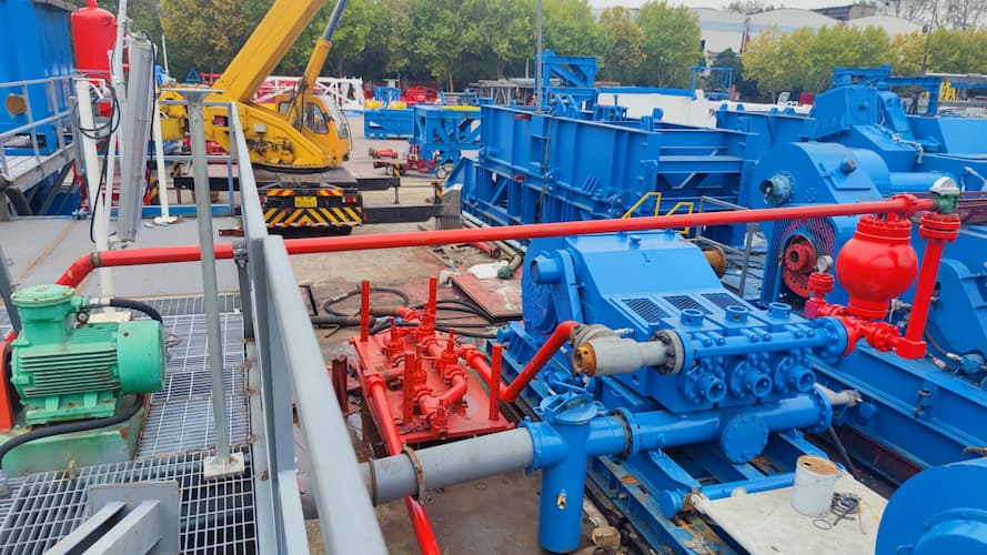
In oil and gas drilling operations, the centrifugal sand pump is one of the core equipment in the solid control system. It is mainly responsible for solid-liquid separation of sand-containing, high-viscosity drilling fluid and transporting it to equipment such as shale shakers and desanders to ensure the progress of drilling operations. High-viscosity drilling fluid (usually referring to viscosity ≥ 50 mPa·s) has the characteristics of poor fluidity, high solid content and high resistance, which puts higher requirements on the performance and structural design of centrifugal sand pumps. Improper selection will not only lead to low pump efficiency and soaring energy consumption, but also cause failures such as pump wear, blockage and overload, seriously affecting drilling progress and increasing costs. Therefore, scientifically and reasonably selecting centrifugal sand pumps is the key to ensuring the treatment effect of high-viscosity drilling fluid and reducing operation costs.
I. Premises for Selection
The core of selection is adaptation, and the premise of adaptation is to fully grasp the inherent characteristics of high-viscosity drilling fluid and the specific requirements of on-site operations, which is the basis for avoiding selection deviations.
(I) Clarify the Core Characteristics of High-Viscosity Drilling Fluid
The characteristics of high-viscosity drilling fluid directly determine the direction of sand pump selection. Focus on the following 3 points: First, viscosity parameters. Clarify the dynamic viscosity and static viscosity of the drilling fluid at the operating temperature (usually 20-80℃). The higher the viscosity, the greater the fluid resistance, and the higher the requirements for the head and power of the sand pump. Second, solid content and particle size. High-viscosity drilling fluid is often accompanied by a large number of cuttings and sand particles. The larger the particle diameter and the higher the content, the more serious the wear on the pump components such as sand pump impellers and sand pump casings, so wear-resistant design should be given priority. Third, density and corrosiveness. Some high-viscosity drilling fluids will add weighting agents (such as barite) or chemical treatment agents. The increase in density will increase the operating load of the pump, and corrosiveness will affect the selection of sand pump materials.
(II) Clarify the Core Requirements of On-Site Operations
Combined with the drilling conditions, clarify the following key requirements: First, flow rate requirements. Determine the rated flow rate (unit: m³/h) required for the sand pump according to the drilling scale and the processing capacity of the solid control system, and reserve a 10%-15% margin to avoid drilling fluid accumulation due to insufficient flow rate. Second, head requirements. Calculate the required rated head (unit: m) based on the drilling fluid transportation distance, pipeline resistance and equipment installation height difference. The pipeline resistance of high-viscosity drilling fluid is much greater than that of ordinary drilling fluid, so the head needs to be appropriately increased. Third, operating environment. Clarify the installation scenario of the sand pump (onshore drilling platform, offshore platform), ambient temperature and explosion-proof requirements. For example, offshore platforms need to select sand pumps with salt spray resistance and corrosion resistance, and flammable and explosive environments need to select explosion-proof motors.
II. Core Selection Indicators
(I) Flow Rate and Head: Adapt to the Actual Needs of High-Viscosity Fluids
Flow rate and head are the basic parameters for sand pump selection, but for high-viscosity drilling fluid, attention should be paid to the difference between "nominal parameters" and "actual parameters". The flow rate and head parameters of ordinary sand pumps are obtained based on clean water tests. When transporting high-viscosity drilling fluid, the fluid resistance increases, the actual flow rate will decrease, and the head will attenuate. The higher the viscosity, the greater the attenuation amplitude. Therefore, during selection, the flow rate and head need to be corrected according to the drilling fluid viscosity: if the drilling fluid viscosity is 50-100 mPa·s, the flow rate and head need to be increased by 15%-20% on the basis of nominal parameters; if the viscosity exceeds 100 mPa·s, it needs to be increased by 20%-30% to ensure that the actual operation can meet the operation requirements.
(II) Impeller Structure: Prioritize High-Viscosity Adaptive Design
The impeller is the core component of the centrifugal sand pump, and its structure directly affects the transportation efficiency and anti-clogging ability of the sand pump for high-viscosity drilling fluid. For high-viscosity drilling fluid, the following two types of impellers are preferred: First, open impeller. The impeller blades have no front and rear covers, with large gaps, which are not easy to be blocked by sand particles and cuttings in the drilling fluid, and are easy to clean and maintain, suitable for drilling fluid with high solid content and high viscosity. Second, wide-channel impeller. The channel width is 20%-30% larger than that of ordinary impellers, which can reduce the flow resistance of high-viscosity fluids, reduce energy consumption, and reduce particle deposition. Avoid using closed impellers (small gaps, easy to block) unless the drilling fluid has been pretreated and the solid content is extremely low.
(III) Material Selection: Balance Wear Resistance and Corrosion Resistance
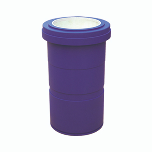
Sand particles and cuttings in high-viscosity drilling fluid will cause severe wear on the flow-through components of the sand pump, and chemical treatment agents may cause corrosion. Therefore, material selection needs to balance wear resistance and corrosion resistance. Common materials are divided into three categories: First, high-chromium alloy (such as Cr27), which has excellent wear resistance, suitable for high-viscosity drilling fluid with high solid content and high sand hardness, and is the most commonly used material in drilling sites. Second, stainless steel (such as 316L), which has strong corrosion resistance, suitable for high-viscosity drilling fluid containing corrosive chemical treatment agents, but its wear resistance is slightly inferior to that of high-chromium alloy. Third, composite materials (such as polyurethane-coated impellers), which have both wear resistance and corrosion resistance, suitable for complex working conditions, but the cost is relatively high, and can be selected according to the budget and working conditions.
(IV) Power and Motor Selection: Match the Requirements of High-Load Operation
The flow resistance of high-viscosity drilling fluid is large, and the sand pump needs more power to overcome the resistance during operation. If the motor power is insufficient, it will cause the sand pump to overload and burn out the motor. During selection, the required shaft power should be calculated according to the corrected flow rate, head, combined with the drilling fluid density and viscosity, and then the appropriate motor power should be selected according to the shaft power. Usually, the motor power needs to be 10%-20% larger than the shaft power to reserve sufficient load margin. At the same time, the motor should be explosion-proof (complying with Exd II BT4 standard) to adapt to the flammable and explosive environment of the drilling site. For offshore platforms, waterproof and salt spray-resistant motors should also be selected.
(V) Speed Control: Prioritize Variable Speed Design
The viscosity of high-viscosity drilling fluid will fluctuate with the drilling process and temperature changes. If the sand pump speed is fixed, when the viscosity increases, the flow rate and head will be greatly attenuated, which cannot meet the operation requirements; when the viscosity decreases, it will cause energy waste. Therefore, centrifugal sand pumps with variable speed are preferred. The speed can be flexibly adjusted according to the change of drilling fluid viscosity through frequency conversion speed regulation or mechanical speed regulation, ensuring that the sand pump is always in the best operating state, which not only guarantees the treatment effect, but also reduces energy consumption.
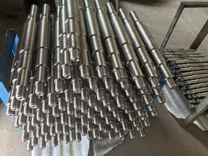
(VI) Sealing Performance: Prevent Drilling Fluid Leakage
High-viscosity drilling fluid has high viscosity and high sand content. If the sealing performance of the sand pump is poor, drilling fluid leakage is likely to occur, which not only pollutes the environment, but also wears components such as shaft sleeves and bearings. During selection, mechanical seals are preferred, which have better sealing performance than packing seals and can adapt to high-viscosity and high-sand working conditions. At the same time, wear-resistant and corrosion-resistant sealing materials (such as silicon carbide and graphite) should be selected to extend the service life of the seal and reduce the maintenance frequency.
III. Practical Selection Steps
Combined with the above premises and core indicators, the selection of centrifugal sand pumps can be completed quickly and accurately in accordance with the following 5 steps to ensure adaptation to high-viscosity drilling fluid conditions.
Step 1: Sort Out Basic Parameters and Clarify Selection Boundaries
Collect and sort out core data: First, drilling fluid parameters (dynamic viscosity, static viscosity, density, solid content, particle size, corrosiveness); second, operation requirements (rated flow rate, transportation distance, installation height difference, operating environment temperature, explosion-proof requirements); third, on-site constraints (installation space, power supply specifications, budget range), clarify the core boundaries of selection, and avoid blind selection.
Step 2: Correct Flow Rate and Head to Match High-Viscosity Conditions
Correct the required flow rate and head according to the drilling fluid viscosity: based on the nominal flow rate and head under clean water conditions, for every 50 mPa·s increase in viscosity, the flow rate and head are increased by 15%-20% respectively. At the same time, further adjust the head parameters combined with the transportation distance and pipeline resistance to ensure that the flow rate and head can meet the processing requirements of the solid control system during actual operation.
Step 3: Screen Core Components and Determine Sand Pump Model
According to the corrected parameters, screen the impeller structure, material and sealing method: prioritize open or wide-channel impellers, select high-chromium alloy (for conventional working conditions) or stainless steel (for corrosive working conditions) as the material, and select double-end mechanical seal as the sealing method; combine the power requirements to select the appropriate motor power and speed control method, and initially determine the sand pump model.
Step 4: Calculate Energy Consumption and Maintenance Costs to Optimize the Selection Plan
Calculate the energy consumption of the initially selected sand pump model, compare the operating power and energy consumption level of different models of sand pumps, and prioritize models with low energy consumption and high efficiency; at the same time, consider the maintenance cost, select sand pumps that are easy to disassemble, maintain and have strong component versatility to reduce subsequent maintenance time and costs. For example, select standardized impellers and seals for on-site replacement.
Step 5: Combine Manufacturer's Technical Support to Finally Confirm the Selection
Provide the sorted basic parameters and corrected selection indicators to the sand pump manufacturer. Combined with the manufacturer's technical support, verify the selection plan - the manufacturer can give a more accurate model recommendation according to its own product characteristics and high-viscosity drilling fluid conditions, and confirm the actual operating performance and adaptability of the sand pump to avoid selection deviations and finally determine the appropriate centrifugal sand pump model.
IV. Selection Pitfall Guide
In the process of selecting sand pumps for high-viscosity drilling fluid, some misunderstandings are likely to occur, leading to the sand pump being unable to adapt to the working conditions and frequent failures. The following are 4 common misunderstandings and corresponding solutions to help avoid selection risks.
Misunderstanding 1: Directly select sand pumps under clean water conditions, ignoring the impact of viscosity
Many selectors directly select according to the flow rate and head under clean water conditions, ignoring the resistance attenuation of high-viscosity drilling fluid, resulting in insufficient actual flow rate and head of the sand pump, which cannot meet the operation requirements. Solution: The flow rate and head must be corrected according to the drilling fluid viscosity, and sufficient margin should be reserved to ensure that the actual operating parameters meet the standards.
Misunderstanding 2: Blindly pursue high parameters, ignoring energy consumption and maintenance costs
Some selectors believe that "the higher the parameters, the better", and select sand pumps with flow rate and head far exceeding the actual needs, leading to soaring energy consumption. At the same time, large-scale sand pumps have higher maintenance costs and larger floor space, resulting in resource waste. Solution: Accurately calculate parameters combined with actual operation needs, avoid over-selection, and prioritize efficient and energy-saving models on the premise of meeting the needs.
Misunderstanding 3: Ignore the wear resistance of materials, leading to rapid component wear
High-viscosity drilling fluid has high sand content. If sand pumps made of ordinary materials are selected, the flow-through components (impellers, pump casings) will wear quickly, leading to shortened sand pump life and frequent failures. Solution: Prioritize wear-resistant materials such as high-chromium alloy. For corrosive working conditions, select stainless steel or composite materials, and regularly check the wear status and replace vulnerable components in time.
Misunderstanding 4: Ignore sealing performance, leading to drilling fluid leakage
Some selectors only pay attention to flow rate and head, ignoring sealing performance, and select sand pumps with packing seals. Under high-viscosity and high-sand working conditions, the seal is easy to fail, leading to drilling fluid leakage. Solution: Prioritize double-end mechanical seals, select wear-resistant and corrosion-resistant sealing materials, ensure the installation accuracy of sealing components, and regularly check the sealing performance and maintain in time.
Read More


 Language :
 English
 Русский
 عربي
عربي
 GET A QUOTE


 IPv6 network supported