facebook linkedin youtube whatsapp
National Unified Hotline :

+86 22 5807 5652

Email Us :

gm@geostarpe.com

#Language :

EnglishEnglish

内页banner

Blogs

Home

Blogs

  • What are the sealing elements of blowout preventers in the oil drilling industry?
    What are the sealing elements of blowout preventers in the oil drilling industry?
    Mar 05, 2025
    In the oil drilling industry, the blowout preventer sealing elements mainly include the following types: Ⅰ. Packing Elements of Annular Blowout Preventer There are two types of annular packing element. Annular Packing Element GK Type: It is conical in shape and generally composed of rubber and a metal framework. Under the action of the hydraulic control pressure oil, the piston moves upward. Restricted by the top cover, the annular packing element is squeezed towards the center of the wellbore under the action of the inner conical surface of the piston, thus sealing the annular space of the wellhead. When there is no drill string in the well, it can fully seal the wellhead. Annular Packing Element Spherical Type:It is hemispherical in shape and is composed of multiple bow-shaped rubber blocks combined with metal hemispherical blocks. When closing the well, the piston pushes the annular packing element to squeeze and deform towards the center of the wellbore to achieve sealing. It has better wear resistance and erosion resistance, and can adapt to higher pressures and harsher working conditions. Advantages of the Packing Elements of the Annular Blowout Preventer: Wide Sealing Range: When there are drill strings, tubing or casing in the well, it can seal various annular spaces of different sizes; when the well is empty, it can fully seal the wellhead. During operations such as drilling, milling, casing grinding, logging, and fishing for downhole lost objects, if there is overflow or blowout, it can seal the space formed between the kelly, cable, wire rope, and the tools for handling accidents and the wellhead. Simple Operation: Only by pushing the piston through hydraulic pressure to make the annular packing element move can the wellhead be closed and opened. The action is rapid, and it can respond quickly to seal the well in case of an emergency. Forcible Tripping and Running of Drill Pipe: With the cooperation of a pressure reducing and regulating valve or a small accumulator, it can perform the operation of forcibly tripping and running drill pipe tools on the 18° butt-welded pipe string joints without fine threads, which improves the flexibility of the operation to a certain extent. Soft Well Closing Function: In case of severe overflow or blowout, it can cooperate with the ram blowout preventer and the choke manifold to achieve soft well closing, which is beneficial to protecting the wellhead equipment and controlling the pressure in the well. Ⅱ. Sealing Elements of Ram Blowout Preventer Ram Rubber Core: It is usually installed on the ram of the ram blowout preventer, and the material is mostly rubber or a composite material of rubber and metal. There are full closing ram rubber cores and half closing ram rubber cores. The full closing ram rubber core is used to fully seal the wellhead when there is no drill pipe; the half closing ram rubber core is used to hold the drill pipe body and seal the annular space between the drill pipe and the wellhead. Advantages of the Sealing Elements of the Ram Blowout Preventer: High Pressure Bearing Capacity: It can withstand high wellhead pressures. Common ram blowout preventer rubber cores can withstand pressures of 35MPa, 70MPa or even higher, ensuring effective sealing under high-pressure working conditions. Good Wear Resistance: Due to frequent contact and friction with the drill pipe, the rubber core material has high wear resistance. For example, wear-resistant materials such as nitrile rubber are used, and wear-resistant fillers are added to extend the service life. Corrosion Resistance: The fluids in oil and gas wells contain corrosive media such as hydrogen sulfide and carbon dioxide. The rubber core material needs to have corrosion resistance. For example, rubbers with good corrosion resistance such as fluororubber are used, or surface anti-corrosion treatment is carried out. Ⅲ. Sealing Elements of Rotating Blowout Preventer Rotating BOP Sealing Element: It is the core sealing component of the rotating blowout preventer and is generally made of special rubber materials. It can achieve wellhead sealing when the drill string is rotating. The rotating bop sealing element is pressed by hydraulic drive to seal the wellhead, and the well sealing pressure can be automatically compensated according to the well pressure. Good Wear Resistance: The rotating bop sealing element needs to be in frequent contact and friction with the rotating and moving up and down drill string. Therefore, rubber materials with good wear resistance, such as nitrile rubber (NBR) or hydrogenated nitrile rubber (HNBR), etc., should be used. High Pressure Resistance: It can withstand a certain wellhead pressure to ensure effective sealing during the operation under pressure and prevent the fluid in the well from spraying out. Temperature and Corrosion Resistance: The fluids in the oil and gas well environment may have characteristics such as high temperature and corrosion. The rotating bop sealing element material should have temperature and corrosion resistance to adapt to different working environments. Ⅳ. To select suitable blowout preventer sealing elements for the oil drilling industry, multiple factors need to be comprehensively considered. The following are the specific selection points: 1.Drilling Working Conditions Pressure and Temperature: Accurately understand the maximum pressure and temperature range that may be encountered during the drilling operation. Different sealing elements have different temperature and pressure resistance performances. For example, in high-temperature and high-pressure wells, fluororubber or metal sealing elements may be more suitable because fluororubber can maintain good sealing performance at relatively high temperatures (up to about 200°C) and high pressures, and metal sealing elements can withstand higher pressures and temperatures; while in low-temperature and low-pressure environments, nitrile rubber sealing elements may be able to meet the requirements. Properties of Drilling Fluid: Determine the type of drilling fluid (such as oil-based drilling fluid, water-based drilling fluid, synthetic-based drilling fluid, etc.), the pH value, as well as the additives and impurities contained in it. Oil-based drilling fluids have higher requirements for the oil resistance of the sealing elements, and nitrile rubber has good resistance to oils; if the drilling fluid is strongly acidic or alkaline, sealing element materials with good chemical corrosion resistance need to be selected, such as fluororubber or some special composite materials. Wellbore Size and Drill String Type: Select suitable sealing elements according to the diameter of the wellbore and the size and type of the drill string (such as drill pipe, drill collar, casing, etc.) used. Different wellbore sizes and drill string combinations require the sealing elements to have corresponding sizes and shapes to ensure a good sealing effect. For example, the annular packing element spherical type has good adaptability to different sizes of drill strings, while the ram rubber core of the ram blowout preventer needs to be selected according to the specific size of the drill string. 2.Performance Characteristics of Sealing Element Sealing Performance: This is the key factor in selecting sealing elements. Consider the sealing reliability of the sealing elements under different working conditions, such as static and dynamic sealing performances. For example, the sealing elements of the rotating blowout preventer need to have good dynamic sealing performance and be able to effectively prevent the fluid in the well from leaking when the drill string is rotating; while the sealing elements of the annular blowout preventer need to be able to achieve reliable sealing in various drill string states (with drill string, without drill string).    Wear Resistance: During the drilling process, the sealing elements will rub against the drill string and drilling fluid, so they need to have good wear resistance. Composite material sealing elements containing reinforcing fibers or particles, or rubber sealing elements with special surface treatment, usually have better wear resistance and can extend the service life.    Elasticity and Recovery: The sealing elements should have good elasticity so that they can quickly return to their original shape after being subjected to pressure and friction to maintain the sealing performance. Rubber sealing elements usually have good elasticity, but different types of rubber also have different elasticities and recovery abilities, and need to be selected according to specific working conditions. 3.Type and Structure of Blowout Preventer Annular Blowout Preventer: For the annular blowout preventer, the Annular Packing Element GK Type and the Annular Packing Element Spherical Type are common sealing elements. The Annular Packing Element GK Type is suitable for general working conditions and has a relatively low cost; the Annular Packing Element Spherical Type has better sealing performance and adaptability to different drill strings, and is suitable for more complex working conditions, but the cost is higher. When selecting, it is necessary to decide according to the specific requirements and budget of the drilling operation. Ram Blowout Preventer: The selection of the ram rubber core should be determined according to the size of the drill string and the wellbore conditions, and the full closing ram rubber core and the half closing ram rubber core should be correctly selected. Rotating Blowout Preventer: The material and structural design of the rotating BOP sealing element have a great influence on its performance, and it is necessary to select products with good rotating sealing performance and durability. 4.Quality and Reliability Quality Certification and Standards: Ensure that the sealing elements meet relevant industry standards and specifications, such as API (American Petroleum Institute) standards, etc. Products with quality certification are more reliable in terms of performance and safety and can meet the strict requirements of the oil drilling industry. 5.Maintenance and Replacement Costs Service Life: The service life of the sealing elements directly affects the maintenance and replacement costs. Selecting sealing elements with a long service life can reduce the replacement frequency, reduce the downtime and maintenance costs. However, it is also necessary to comprehensively consider its initial purchase cost and conduct an economic analysis. Maintainability: Consider the ease of installation, disassembly, and replacement of the sealing elements. Some sealing elements are designed for easy maintenance and replacement, which can improve work efficiency and reduce maintenance costs. At the same time, consider the universality of the sealing elements so that spare parts can be conveniently obtained when needed. Ⅴ. In the oil drilling industry, various factors will affect the service life of the sealing elements. The following is a specific introduction: 1.Working Environment Factors Pressure: Excessive pressure will make the sealing elements bear a large load, resulting in deformation, wear, or even cracking. In a high-pressure environment, the friction force between the sealing elements and the sealing surface increases, accelerating the wear of the sealing elements and shortening their service life. For example, when the pressure in the well exceeds the designed bearing pressure of the sealing elements, the rubber part of the sealing elements may be extruded or torn. Temperature: Temperature has a significant impact on the performance of the sealing elements. High temperatures will accelerate the aging of rubber sealing elements, making them hard and brittle, and reducing their elasticity and sealing performance; low temperatures may cause the rubber sealing elements to lose their elasticity and become stiff, unable to seal effectively. For example, fluororubber sealing elements have good performance in high-temperature environments, but they may harden in low-temperature environments. Chemical Media: Various chemical substances contained in the drilling fluid, such as acids, alkalis, salts, oils, etc., will corrode the sealing elements. Different materials of the sealing elements have different tolerances to chemical media. For example, nitrile rubber has good tolerance to oils, but it is easily corroded in a strong acid and alkali environment; while fluororubber has better chemical corrosion resistance. Particle Impurities: Solid particle impurities carried in the drilling fluid, such as cuttings, sand grains, etc., will scour and wear the surface of the sealing elements during the flow process. These particle impurities will scratch the surface of the sealing elements, damage their sealing performance, lead to leakage, and thus shorten the service life of the sealing elements. 2.Factors of the Sealing Elements Themselves Material Quality: The material quality of the sealing elements directly determines their performance and service life. High-quality materials have better elasticity, wear resistance, corrosion resistance, and high-temperature resistance. For example, sealing elements made of high-quality rubber materials have better elasticity and aging resistance and can maintain good sealing performance for a long time in harsh working environments. Structural Design: A reasonable structural design can make the sealing elements better adapt to the working environment and reduce stress concentration and wear. For example, the shape, size of the sealing elements, and the design of the sealing lips will all affect their sealing performance and service life. A reasonably designed sealing element can evenly distribute the pressure during operation and reduce local wear. Manufacturing Process: The quality of the manufacturing process will affect the precision and quality of the sealing elements. A precise manufacturing process can ensure the dimensional accuracy and surface quality of the sealing elements and reduce internal defects and stress concentration. For example, rubber sealing elements manufactured by advanced molding processes have a more uniform internal structure and more reliable quality. 3.Maintenance and Repair Factors Regular Inspection and Maintenance: Regularly inspect and maintain the sealing elements, and promptly discover and deal with problems such as wear, aging, and damage of the sealing elements, which can extend their service life. If the inspection is not carried out regularly, small problems of the sealing elements may gradually develop into major problems, leading to sealing failure. Storage Conditions: The sealing element should be placed in a dry and dark room with a constant temperature throughout the year (below 27°C) and should never be exposed to the wind, sun, and rain outdoors. The sealing element should be kept away from electrical equipment that generates arcs, such as motors and electric welders, to prevent ozone corrosion. The sealing element should be placed flat individually and should not be squeezed or stacked. Bending, extrusion, and hanging are strictly prohibited. During the inspection, if it is found that the sealing element is brittle, cracked, bent, or has cracks, it should no longer be used.
    Read More
  • What are the different types of mud pump liners?
    What are the different types of mud pump liners?
    Feb 28, 2025
    The liners of mud pumps include bi-metal liners and ceramic liners, each having its own characteristics. Below, we will introduce these two types of liners in detail from the following aspects. Ⅰ. Bi-Metal Liners of Mud PumpsThe Bi-Metal liner is a cylinder liner composed of two different metallic materials and is widely applied in the industrial field. The following is a detailed introduction to it:Advantages Good Wear Resistance: Usually, the inner layer is made of high-hardness wear-resistant alloys, such as high-chromium cast iron. These materials have high hardness and can effectively withstand the erosion and wear of materials, making them suitable for use when transporting media containing solid particles. High Strength and Toughness: The outer layer of metal generally uses steel with higher strength, such as carbon steel, which provides good mechanical strength and toughness, enabling the cylinder liner to withstand greater pressure and impact loads. In some working conditions with complex situations and large impact forces, the Bi-Metal liner can ensure the normal operation of the equipment. Good Corrosion Resistance: The inner layer of some bi-metal liners uses metallic materials with better corrosion resistance, such as stainless steel. This allows the cylinder liner to resist the erosion of corrosive media like acids and alkalis to a certain extent, making it suitable for transporting liquids with a certain degree of corrosiveness. High Cost-effectiveness: Compared with some high-performance liners made of a single material (such as pure ceramic liners), the bi-metal liner reduces costs by reasonably combining two metallic materials while meeting certain performance requirements. For some projects that are sensitive to costs, the bi-metal liner is an economical and practical choice. Strong Repairability: During the use process, if the liner suffers from local wear or damage, since it is mainly composed of metallic materials, it can be repaired through metal processing techniques such as surfacing and repair welding. The repair cost is relatively low, and the operation is relatively simple, which can effectively extend the service life of the equipment and reduce the frequency of equipment replacement.Manufacturing Process Centrifugal Casting of the Inner Sleeve: Pour the molten high-chromium cast iron liquid into a high-speed rotating mold. Under the action of centrifugal force, the iron liquid adheres evenly to the inner wall of the mold, and after cooling, the inner sleeve is formed. This process can make the inner sleeve have a dense structure without shrinkage cavities, air holes, and other defects, ensuring the quality and performance of the inner sleeve. Hot Pressing Molding of the Outer Sleeve: Heat the high-quality carbon steel billet to an appropriate temperature, put it into the mold, and perform one-time hot pressing molding through a press to make the outer sleeve reach the required size and shape, obtaining good strength and toughness. Insertion and Assembly: Insert and assemble the processed inner sleeve and outer sleeve. Usually, an interference fit method is adopted to make the two combine closely to form an integral bi-metal liner to meet the usage requirements of the mud pump.Application Scenarios In the Petroleum Drilling Field: In onshore petroleum drilling, it is used for drilling operations in ordinary formations and can withstand conventional mud pressure and wear. On offshore petroleum drilling platforms, it can also meet the operation requirements to a certain extent, providing a reliable channel for the circulation and transportation of mud. Ⅱ. Ceramic Cylinder Liners of Mud PumpsCeramic liners are widely used in the industrial field. The following is a detailed introduction to them:Advantages High Wear Resistance: Ceramic materials have extremely high hardness. For example, alumina ceramics, zirconia ceramics, etc., have a Mohs hardness of about 9, second only to diamond. This enables the ceramic liner to effectively resist the wear caused by solid particles, fluid erosion, etc. In working conditions where highly abrasive media such as mineral slurries, coal powders, and sand and gravel are transported, it shows excellent wear resistance and greatly extends the service life of the equipment. Excellent Corrosion Resistance: Ceramics have good chemical stability and hardly react with chemical substances such as acids, alkalis, and salts. Therefore, the ceramic liner can remain stable in a strongly corrosive environment. Using a ceramic liner can effectively prevent the equipment from being corroded and ensure the safe and stable operation of production. Good High-temperature Resistance: Many ceramic materials have a high melting point and good thermal stability, and can maintain their physical and chemical properties in a high-temperature environment. Smooth Surface and Low Friction Coefficient: The surface of the ceramic liner is extremely smooth, and the friction coefficient is much lower than that of other materials such as metals. This significantly reduces the resistance when the fluid flows in the pipeline, not only improving the transportation efficiency but also reducing energy consumption. At the same time, the smooth surface also reduces the adhesion and accumulation of materials on the inner wall of the pipeline, which is beneficial to keeping the pipeline unobstructed.There are also mud pump ZTA liners and pure zirconia cylinder liners among ceramic cylinder liners. The following introduces the characteristics of these two types of ceramic cylinder liners. Ⅲ. ZTA Ceramic Cylinder LinersManufacturing Process Batching and Mixing: Accurately weigh raw materials such as alumina and zirconia in a certain proportion, add additives, and put them into a ball mill for uniform mixing to form a uniform green body. Molding: Use methods such as dry pressing molding and isostatic pressing molding to form the mixed raw materials into a green body of the required shape. Sintering: Put the green body into a high-temperature furnace for sintering. At a high temperature of 1600-1800°C, the raw materials undergo a solid-phase reaction to form a dense ZTA ceramic. Processing and Assembly: Cut, grind, polish, and perform other processing on the sintered ceramic to make it reach the required size and accuracy, and then use the vulcanization process to composite and assemble the ZTA ceramic with rubber, steel plates, etc.Advantages Compared with Other Cylinder LinersCompared with ordinary alumina ceramic liners, ZTA ceramic liners have better toughness and impact resistance and a longer service life. Compared with metallic liners, ZTA ceramic liners have higher hardness, wear resistance, and corrosion resistance, and can maintain good performance under harsh working conditions, reducing equipment maintenance and replacement costs. Ⅳ. Pure Zirconia Cylinder LinersIt refers to a liner mainly made of zirconia, and its zirconia content is usually above 95%. The following is a detailed introduction:Material Characteristics High Purity: The main component is zirconia, and the purity is generally above 95%. A small amount of stabilizers, such as yttria, may be added to improve its performance. High Density: It has a relatively high density, generally about 6.0 grams per cubic centimeter. Stable Chemical Properties: It has excellent chemical stability and can withstand the corrosion of various acids, alkalis, and other chemical substances.Performance Advantages Good Wear Resistance: It has excellent wear resistance and can effectively resist the erosion and wear of solid particles in the medium, extending the service life of the equipment. High Temperature Resistance: It can withstand a high temperature of up to 800°C and has good thermal stability. Strong Corrosion Resistance: It has excellent tolerance to various corrosive media and can maintain stable performance in a harsh chemical environment. Good Electrical Insulation: It has good electrical insulation performance and can be used in some occasions where electrical insulation is required.Manufacturing Process Raw Material Preparation: Select high-purity zirconia powder as the main raw material, and a small amount of additives can be added according to needs. Uniformly mix the raw materials through ball milling to prepare the required powder material. Processing: Cut, grind, polish, and perform other processing on the sintered zirconia cylinder liner to make its size and accuracy reach the required standards.Application Scenarios In Petroleum and Natural Gas Drilling: In the mud pumps for petroleum and natural gas drilling operations, it can withstand the erosion of high-pressure mud and solid particles.Cost and Service Life High Cost: Due to the high cost of raw materials and the complex manufacturing process, the production cost of pure zirconia liners is relatively high, and their price is also more expensive than that of some ordinary liners. Long Service Life: With its excellent performance, the service life of pure zirconia liners is relatively long. Ⅴ. Comparison between Ceramic Cylinder Liners and Bi-Metal Liners of Mud PumpsCeramic liners and metallic bi-metal liners of mud pumps each have their own advantages and applicable scenarios. The following is a comparative analysis from multiple aspects: 1.Wear Resistance Ceramic Cylinder Liners: Ceramic materials have extremely high hardness. For example, alumina ceramics, zirconia ceramics, etc., and their wear resistance is usually much better than that of metallic materials. Taking zirconia ceramics as an example, it can effectively resist the erosion and wear of solid particles in the mud. For mud containing a large number of sharp and high-hardness particles, the wear rate of the ceramic liner is very slow, and the service life is long. Bi-metal Cylinder Liners: Wear-resistant metallic materials such as high-chromium cast iron also have good wear resistance, but there is still a gap compared with ceramics. When transporting highly abrasive mud for a long time, the wear of the bi-metal liner is relatively fast, and the liner needs to be replaced more frequently, increasing the maintenance cost and downtime. 2.Corrosion Resistance Ceramic Cylinder Liners: Ceramics have good chemical stability and hardly react with chemical substances such as acids and alkalis. When transporting strongly corrosive mud, they can maintain the integrity and performance stability of the liner. Bi-metal Liners: Some bi-metal liners (such as duplex stainless white iron, etc.) have a certain degree of corrosion resistance, but in a strongly corrosive environment, the metal may still corrode, leading to the damage to the liner. Even metallic materials with better corrosion resistance are difficult to compare with ceramics in terms of corrosion resistance. 3. Strength and Toughness Mud Pumps with Ceramic Liners: The disadvantage of ceramic materials is that their toughness is relatively low and they are more brittle. When subjected to large impact loads, the ceramic liner may crack or even break. Although some ceramic toughening technologies have developed in recent years, the toughness of ceramics is still not as good as that of metals. In working conditions where the mud pump may encounter large impact forces, the reliability of the ceramic liner will be affected to a certain extent. Mud Pumps with Bi-Metal Liners: Metallic materials have good strength and toughness and can withstand large impacts and pressures. In some working conditions with complex situations and possible large impact forces, such as when the drilling mud pump works in an unstable formation, the bi-metal liner can better adapt to such working conditions and reduce the risk of damage caused by impacts. 4. Cost Ceramic Liners: Due to the relatively high price of ceramic materials themselves and the relatively complex manufacturing process, the initial purchase cost of mud pumps with ceramic liners is relatively high. In addition, due to the high requirements for the processing and installation of ceramic liners, the maintenance cost is also relatively high. Bi-Metal Liners: The manufacturing cost of bi-metal liners is relatively low, and the processing and maintenance technologies of metallic materials are relatively mature, and the maintenance cost is also low. 5.  Applicable Working Conditions Ceramic Liners: They are more suitable for use in working conditions with high abrasion, high corrosion, high requirements for the purity of the mud (ceramics are not likely to contaminate the mud), but with small impact loads. Bi-Metal Liners: They are suitable for working conditions with more complex situations, possible large impact loads, and where the requirements for wear resistance and corrosion resistance are not extremely high. 6.Service Life Bi-Metal Liners: Under normal working conditions, the service life is generally more than 800 hours. Zirconia Ceramic Liners: It has a relatively long service life, usually reaching more than 4,000 hours, which is several times that of the bimetallic cylinder liner. In conclusion, if the working conditions are mainly characterized by high abrasion and high corrosion with small impact loads, the ceramic liner is a better choice; while if the working conditions are complex, with large impact loads and a sensitivity to costs, the bi-metal liner is more appropriate.Cylinder liners for models like F1000 mud pump liner and F1600 mud pump liner are available in various materials.    
    Read More
  • What is a shale shaker?
    What is a shale shaker?
    Feb 25, 2025
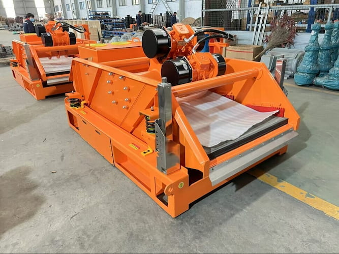
         The shale shaker is a crucial piece of equipment in the oil and gas drilling industry, mainly used for solid control in the drilling fluid system. The following is a detailed introduction: Ⅰ. Structure Screen Box: It is the main part of the shale shaker, usually fabricated from high-strength steel plates. The screen box serves to support the screen mesh and is designed to withstand the vibrations generated during operation. Screens Mesh for Shale Shaker and Mud Cleaner: This is a key component for separating solid particles from the drilling fluid. Screen meshes are available in various materials, such as stainless steel wires and polyurethane. Moreover, different mesh counts of the screen mesh are employed according to the required separation precision. Vibrator: The vibrator is responsible for inducing vibrations in the screen box. It is typically an electric motor equipped with an eccentric block. When the motor rotates, the eccentric block generates a centrifugal force, causing the screen box to vibrate. Feeding Device: It is used to distribute the drilling fluid evenly onto the screen mesh. This ensures that the entire screen surface can be effectively utilized for the separation operation. Underflow Collection System: After the drilling fluid passes through the screen mesh, the liquid portion (underflow) will be collected in a container or channel for further processing. Ⅱ. Working PrincipleThe drilling fluid shale shaker is an essential piece of equipment in oil and gas drilling operations, etc., used for separating solid particles (such as cuttings) from the drilling fluid. Its working principle is mainly based on vibration and screening, as detailed below: Vibration Generation: The shale shaker is usually driven by vibration motors, which are fitted with eccentric blocks. When the vibration motors are powered on and operate, the eccentric blocks rotate at high speed along with the motor shafts. Since the center of gravity of the eccentric blocks deviates from the center of the rotation axis, a centrifugal force is generated during the rotation process. This centrifugal force causes the vibration motors to vibrate, which in turn drives the entire screen box to vibrate. Depending on the configuration and installation method of the vibration motors, the vibration trajectory of the screen box can be categorized into linear, circular, or elliptical. Linear Vibration: When two vibration motors rotate synchronously and in opposite directions, the vibration forces generated by the eccentric blocks cancel each other out in the direction parallel to the motor axes and combine into a resultant force in the direction perpendicular to the motor axes, causing the screen box to move linearly. This linear vibration mode is suitable for the screening of fine-grained materials, enabling the materials to jump linearly on the screen surface, which helps to improve the screening accuracy. Circular Vibration: If there is only one vibration motor or two motors work in a specific coordinated manner, the screen box will generate a circular vibration trajectory. In circular vibration, the materials move in a circular path on the screen surface. This movement pattern has a good effect of lifting and loosening the materials and is suitable for processing coarse-grained materials, offering a relatively large processing capacity. Elliptical Vibration: It combines the characteristics of linear vibration and circular vibration. By adjusting the parameters and installation angles of the vibration motors, the screen box can generate an elliptical vibration trajectory. Elliptical vibration can not only ensure a certain screening accuracy but also provide a relatively large processing capacity, making it suitable for the screening of materials under various working conditions. Material Screening: The drilling fluid containing solid particles (such as cuttings) is evenly conveyed to the surface of the screen mesh through the feeding device. Due to the vibration of the screen box, the drilling fluid on the screen mesh is subjected to the combined action of the vibration force and its own gravity. Smaller particles (including fine solid particles that meet the requirements and the liquid phase) can pass through the mesh holes of the screen mesh and fall into the collection device below the screen box, becoming the undersize product (underflow); while larger solid particles (such as cuttings) cannot pass through the screen mesh, and they keep jumping and moving on the screen surface, gradually moving towards the discharge end of the screen mesh and finally being discharged from the discharge port, becoming the oversize product.      In actual operation, operators can also, based on the properties of the drilling fluid (such as solid phase content, particle size distribution, etc.) and processing requirements, adjust parameters such as the rotation speed of the vibration motors and the angles of the eccentric blocks to change the vibration frequency, amplitude, and vibration trajectory of the screen box, thereby optimizing the screening effect of the shale shaker and improving the processing efficiency and quality of the drilling fluid. Ⅲ. Role in Drilling Operations Removal of Solid Particles: Its primary function is to remove larger solid particles (cuttings) from the drilling fluid. By doing so, it helps to maintain the appropriate properties of the drilling fluid, such as density, viscosity, and fluid loss characteristics. This is of vital importance for the smooth progress of drilling operations. Recycling of Drilling Fluid: After the solid particles are removed, the drilling fluid can be recycled, reducing the cost of replacing the drilling fluid and minimizing the environmental impact. Equipment Protection: By reducing the solid content in the drilling fluid, the shale shaker helps to protect downstream equipment, such as pumps and other solid control devices, from excessive wear and tear.       Selecting a suitable drilling shaker requires comprehensive consideration of multiple factors to ensure that it can meet the needs of drilling operations. The following are some key considerations: Processing Capacity: Determine the processing capacity of the shaker according to the scale of the drilling operation and the expected amount of drilling fluid generated. Generally speaking, a shaker with a larger processing capacity can handle more drilling fluid per unit time. Factors such as the flow rate, density, and solid phase content of the drilling fluid should be taken into account, and a shaker that can effectively handle these parameters should be selected. If the processing capacity is insufficient, it may lead to the overflow of drilling fluid, affecting the operation efficiency and quality. Screening Precision: Select an appropriate screening precision according to the requirements for removing solid particles from the drilling fluid in the drilling operation. Different drilling operations may require screen meshes of different particle sizes to ensure that the unwanted solid particles can be effectively separated. Common screen mesh counts range from dozens to hundreds. The higher the mesh count, the higher the screening precision. For example, in some operations with high requirements for the purity of the drilling fluid, a screen mesh with a high mesh count may need to be selected. Vibration Mode: Common vibration modes of drilling shakers include linear vibration, circular vibration, and elliptical vibration. The linear vibration shaker is suitable for the screening of fine-grained materials and features high screening precision; the circular vibration shaker has a larger processing capacity and is suitable for the screening of coarse-grained materials; the elliptical vibration shaker combines the advantages of linear vibration and circular vibration, offering a better screening effect and processing capacity. Select an appropriate vibration mode according to the actual drilling operation requirements and material characteristics. Screen Mesh Material: The screen mesh is a crucial component of the drilling shaker, and its material directly affects the screening effect and service life. Common screen mesh materials include metal wire woven meshes, polyurethane screen meshes, etc. The metal wire woven mesh has high strength and wear resistance, making it suitable for processing large-particle materials and high-concentration drilling fluid; the polyurethane screen mesh has good elasticity and corrosion resistance, which can effectively prevent materials from blocking the screen holes, improve the screening efficiency, and is suitable for processing fine-grained materials and drilling fluid with strong corrosiveness. Select an appropriate screen mesh material according to the properties of the drilling fluid and material characteristics. Reliability and Durability: Consider the structural design, manufacturing process, and material quality of the shaker, and select products with high reliability and durability. High-quality shakers should be made of high-strength materials and adopt advanced manufacturing processes to ensure long-term stable operation in harsh drilling environments. Check the brand reputation, user reviews, and after-sales service of the equipment, and choose suppliers with a good reputation and a complete after-sales service system to ensure that the equipment can be repaired and supported in a timely manner when a malfunction occurs. Energy Consumption and Maintenance Cost: Select a shaker with relatively low energy consumption to reduce the cost of drilling operations. At the same time, consider the maintenance cost of the equipment, including factors such as the replacement frequency of the screen mesh, the price of spare parts, and their availability. Some shakers have a reasonable design, with convenient screen mesh replacement and strong versatility of spare parts, which can reduce the maintenance cost and downtime. Compatibility with Existing Equipment: Ensure that the selected drilling shaker can be compatible with the existing drilling equipment and solid control system. Consider factors such as the interface size, installation method, and control mode of the shaker to ensure that it can be smoothly integrated into the existing drilling system and achieve efficient collaborative operation. Safety Performance: Check whether the shaker is equipped with necessary safety protection devices, such as protective covers, anti-slip devices, etc., to ensure the safety of operators. Understand the vibration and noise level of the equipment, and select products that meet the safety standards and environmental protection requirements to avoid causing adverse effects on the operators and the surrounding environment. Ⅳ. Shaker Models       ZS-752 shaker screen Application Areas Horizontal Directional Drilling (HDD) without Excavation: In trenchless construction projects such as laying underground pipelines, it is used to process the drilling fluid, separate solid particles such as cuttings from it, and ensure the performance and recycling of the drilling fluid. Water Well Drilling: In water well drilling operations, it is used for the solid-liquid separation of the drilling fluid generated during the drilling process, removing impurities, and improving the drilling efficiency and the quality of the water well. Diamond Core Drilling: It is used to process the drilling fluid in the diamond core drilling process, separating solid particles such as cuttings from the drilling fluid, which helps to protect the drilling equipment and improve the drilling accuracy. Product Features High Screening Efficiency: With advanced linear vibration technology and a reasonable screen mesh design, it can effectively separate solid particles of different particle sizes and improve the quality of the drilling fluid. Excellent Material Quality: The screen mesh is made of high-strength and corrosion-resistant stainless steel materials, and the screen frame is made of high-quality steel. After precise processing and heat treatment, it has good wear resistance, high strength, and strong stability. Reliable Operation: Equipped with advanced motors and a control system, it has overload protection and fault alarm functions, which can ensure the stable operation of the equipment and guarantee the safety of the operation.        ZS-583 shaker screen Application Areas Oil and Gas Drilling: In the exploration and development of oil and gas, it is used to process the drilling fluid, separate solid phase particles such as cuttings from it, ensure the performance of the drilling fluid, improve the drilling efficiency, and reduce the cost. Coalbed Methane Development: In the coalbed methane drilling process, it is used for the solid-liquid separation of the drilling fluid, removing impurities, and providing a guarantee for the subsequent coalbed methane extraction. Horizontal Directional Drilling: In trenchless projects such as laying underground pipelines, it is used to process the mud generated during the drilling process, enabling the mud to be recycled and improving the construction efficiency. Product Features Large Processing Capacity: With a relatively large screen mesh area and a reasonable structural design, it can efficiently process a large amount of drilling fluid. High Screening Precision: According to different drilling requirements, screen meshes with appropriate mesh counts can be selected to effectively separate solid particles of different particle sizes. Good Stability: Using high-quality materials and advanced manufacturing processes, the equipment operates stably and reliably and can adapt to harsh working environments. Easy Operation and Maintenance: It has a simple and easy-to-understand operation interface, which is convenient for the staff to operate and maintain. Moreover, the screen mesh is easy to replace.        ZS-584 shaker screenApplication Areas Oil and Gas Drilling: It is used to process the drilling fluid and separate solid phase particles such as cuttings to ensure the performance of the drilling fluid. Coalbed Methane Development: In the drilling process, it is used for the solid-liquid separation of the drilling fluid and removing impurities. Other Drilling Projects: Such as geological exploration, geothermal drilling, and other fields, it is used for the solid-liquid separation of the mud in the drilling process.Product Features High Excitation Intensity: The excitation intensity can reach up to 8.0G and is adjustable, which can effectively separate the solid phase and the liquid phase and dry the cuttings. Stable Operation: The screen box undergoes integral heat treatment, which enables it to work stably for a long time under high excitation intensity; the thermal relay in the electrical control box has overload and phase failure protection functions. Convenient Feeding: The hopper feeding method effectively reduces the feeding height, making it convenient for the conveyor to feed.        ZS-585S shaker screenApplication Areas       Similar to other similar shale shakers, it is widely used in oil and gas drilling, coalbed methane development, horizontal directional drilling, diamond core drilling, water well drilling, and other fields for the solid-liquid separation of the drilling fluid. Product Features Large Processing Capacity: With a relatively large screen mesh area and high vibration intensity, it can handle a large amount of drilling fluid, meeting the needs of drilling operations of different scales. High Screening Precision: According to the size of the solid phase particles in the drilling fluid, screen meshes with appropriate mesh counts can be selected to effectively separate solid particles of different particle sizes and improve the purification effect of the drilling fluid. Good Stability: The screen box has undergone integral heat treatment, which enables it to work stably for a long time under high excitation intensity; the equipped vibration motors and electrical components are mostly from well-known brands, and the operation is reliable. Easy Operation and Maintenance: It has a simple and easy-to-understand operation interface, which is convenient for the staff to operate and maintain. The screen mesh is easy to replace, and the disassembly and installation of the screen mesh can be completed quickly, improving the work efficiency. Ⅴ. Screen Mesh Materials      The reasonable selection of the screen mesh material and aperture of the shale shaker is of great significance for ensuring the treatment effect of the drilling fluid, improving the screening efficiency, and extending the service life of the screen mesh. The following is a detailed introduction: 1.Metal Wire Woven Mesh  Material Characteristics: Common types include stainless steel wires (such as 304 and 316 stainless steel), low-carbon steel wires, etc. Stainless steel wires have good corrosion resistance and can adapt to various chemical components that may be present in the drilling fluid, especially suitable for processing corrosive drilling fluid; low-carbon steel wires have high strength and wear resistance and are relatively low in cost.   Application Scenarios: In the processing of large-particle and high-concentration drilling fluid, or in working conditions with high requirements for wear resistance, the metal wire woven mesh performs outstandingly. For example, in some shallow drilling operations or drilling operations in complex geological conditions with larger cutting particles, this screen mesh can withstand greater impact forces and wear. 2.Polyurethane Screen Mesh Material Characteristics: Polyurethane is a polymer synthetic material with excellent elasticity and wear resistance. Its elasticity can effectively prevent materials from blocking the screen holes, and it can maintain a high screening efficiency even when processing viscous drilling fluid. In addition, the polyurethane screen mesh also has good corrosion resistance and can adapt to a variety of chemical environments.  Application Scenarios: It is suitable for processing fine-grained materials and drilling fluid with strong corrosiveness. In deep drilling operations or operations with high requirements for the purification of the drilling fluid, the polyurethane screen mesh can more precisely separate out fine solid phase particles and improve the purity of the drilling fluid. At the same time, due to its good elasticity and wear resistance, its service life is relatively long. 3.Composite Screen Mesh Material Characteristics: It is composed of metal wires and materials such as polyurethane. Usually, the metal wires serve as the framework to provide strength and support, and the polyurethane covers the surface of the metal wires to play the roles of wear resistance and anti-blocking. This composite structure combines the advantages of the strength of the metal wires and the elasticity and wear resistance of the polyurethane. Application Scenarios: It is suitable for various complex drilling working conditions. It can not only process large-particle cuttings but also effectively separate fine solid phase particles. At the same time, it also has good corrosion resistance and anti-blocking performance. In some drilling operations with high requirements for the comprehensive performance of the screen mesh, the composite screen mesh is a good choice. Ⅵ. Screen Mesh Aperture Particle Size of Solid Phase in Drilling Fluid: This is the most important basis for selecting the screen mesh aperture. It is necessary to analyze the particle size distribution of the solid phase particles in the drilling fluid and understand the content of particles of different particle sizes. Generally speaking, the screen mesh aperture should be slightly smaller than the maximum particle size of the solid phase particles to be separated to ensure that these particles can be effectively intercepted. For example, if most of the solid phase particles in the drilling fluid have a particle size between 0.1-0.5mm, then a screen mesh with an aperture of 0.08-0.4mm can be selected to achieve a better screening effect. Drilling Operation Stage: The properties of the drilling fluid and the composition of the solid phase particles will change at different stages of the drilling operation. In the initial stage of drilling, it may mainly be loose materials on the surface of the earth, with larger particles; as the drilling depth increases, the cutting particles will gradually become smaller. Therefore, it is necessary to adjust the screen mesh aperture according to the actual situation at different stages. For example, in the initial stage of drilling, a screen mesh with a larger aperture can be used to quickly remove larger particles; in the later stage of drilling, it can be replaced with a screen mesh with a smaller aperture to further purify the drilling fluid. Performance Requirements of Drilling Fluid: Different drilling operations have different requirements for the performance of the drilling fluid, such as density, viscosity, and sand content. The selection of the screen mesh aperture should help meet these performance requirements. If a lower sand content of the drilling fluid is required, a screen mesh with a smaller aperture needs to be selected to separate out as many solid phase particles as possible; if a higher viscosity of the drilling fluid is required, it may be necessary to appropriately adjust the screen mesh aperture to avoid excessive screening, which may lead to the loss of useful components in the drilling fluid. Ⅶ. Daily Maintenance Techniques 1.Screen Mesh Maintenance Check the Wear Condition of the Screen Mesh: Before starting the equipment each time and during its operation, inspect the surface of the screen mesh for any damage, holes, or severely worn areas. Pay special attention to the edges and fixed parts of the screen mesh, as these areas are prone to damage due to stress concentration. If the screen mesh is found to be severely worn, it should be replaced in a timely manner to avoid affecting the screening effect and the operation of the equipment. Clean the Blockages on the Screen Mesh: The solid-phase particles in the drilling fluid may block the holes of the screen mesh, reducing the screening efficiency. Regularly (such as every few working hours) use a soft brush or a special screen mesh cleaning tool to clean the blockages on the surface of the screen mesh. Avoid using sharp tools to prevent damage to the screen mesh. For highly viscous blockages, the screen mesh can be rinsed with low-pressure water, but be careful not to use excessive pressure, as it may damage the structure of the screen mesh. Adjust the Tension of the Screen Mesh: The tension of the screen mesh has an important impact on the screening effect. A screen mesh that is too loose will cause the materials to slide on the screen surface, affecting the screening efficiency and may also accelerate the wear of the screen mesh; a screen mesh that is too tight may be damaged prematurely due to excessive stress. Regularly check the tension of the screen mesh and adjust it as needed. Generally speaking, the screen mesh should make a clear and crisp sound after being tensioned. 2.Vibration Motor Maintenance  Check the Motor Temperature: During the operation of the equipment, frequently check the temperature of the vibration motor. If the motor temperature is too high, it may be caused by reasons such as excessive load, poor heat dissipation, or motor failure. Once the motor temperature is found to be abnormal, stop the machine immediately for inspection, identify the cause, and deal with it in a timely manner. Tools such as an infrared thermometer can be used to measure the surface temperature of the motor. Lubricate the Motor Bearings: According to the recommendations of the motor manufacturer, regularly lubricate the bearings of the vibration motor. Use appropriate lubricating grease and ensure that the amount of lubricating grease added is appropriate. Too much or too little lubricating grease may affect the service life of the bearings. When adding lubricating grease, pay attention to cleanliness and avoid impurities from entering the bearings. Tighten the Motor Mounting Bolts: The vibration motor will generate vibrations during operation, which may cause the mounting bolts to loosen. Regularly check and tighten the mounting bolts of the motor to prevent the motor from loosening and affecting the normal operation of the equipment and the vibration effect. 3.Screen Box and Other Components Maintenance Check the Connection Parts of the Screen Box: Inspect all the connection parts of the screen box, such as bolts, nuts, and welding points, to ensure that they are firm and reliable. Loose connection parts may cause abnormal vibrations of the screen box and even lead to equipment failures. When loose connection parts are found, tighten them in a timely manner. Clean the Debris Inside the Screen Box: Regularly clean the debris and residual drilling fluid inside the screen box to keep the interior of the screen box clean. The accumulation of debris may affect the vibration effect of the equipment and may also corrode the internal components of the screen box. Check the Vibration Damping Device: The shale shaker is usually equipped with a vibration damping device, such as a vibration damping spring or a rubber shock absorber. Check whether these vibration damping devices are damaged, deformed, or aged. If the vibration damping device fails, it will cause excessive vibrations of the equipment, affecting the stability and service life of the equipment, and it should be replaced in a timely manner. 4.Electrical System Maintenance Check the Electrical Circuits: Regularly inspect the electrical circuits of the equipment for any damage, aging, short circuits, or other problems. Ensure that the connections of the electrical circuits are firm and that there are no loose plugs or sockets. For damaged electrical circuits, replace them in a timely manner to ensure the electrical safety of the equipment. Clean the Electrical Control Box: The dust and debris inside the electrical control box may affect the normal operation of the electrical components. Regularly clean the interior of the control box to keep it dry and clean. Compressed air can be used to blow away the dust, and avoid using a damp cloth to wipe it to prevent short circuits.        By following the above daily maintenance techniques, the service life of the shale shaker can be effectively extended, its work efficiency and reliability can be improved, and the smooth progress of drilling operations can be ensured.    
    Read More
  • What is the difference between Kelly Drive and top drive?
    What is the difference between Kelly Drive and top drive?
    Feb 21, 2025
    The main differences between the kelly drive and the top drive are as follows: Ⅰ. Main differences Structural Location:The kelly drive device is mainly composed of a rotary table, a swivel, a kelly, etc. The rotary table is on the drill floor and cooperates with the kelly through a kelly bushing. The top drive drilling system is generally installed at the top of the derrick and includes components such as the swivel-drilling motor assembly, the motor support/guide trolley assembly, and the drill pipe make-up and break-out assembly. Driving Method:The power of the kelly drive device comes from the ground rotary table. It drives the kelly to rotate through the kelly bushing, and then drives the drill string and the drill bit. The top drive is directly driven by the drilling motor installed at the top of the derrick to rotate the top of the drill pipe. Drilling Mode:The kelly drive device adopts single joint drilling. After drilling a length of one kelly (about 9 meters), a joint connection operation is required. The top drive adopts stand drilling. A stand is usually composed of three drill pipes, with a length of approximately 28 meters Well Control Operation:In the case of well kicks and other situations during tripping operations with the kelly drive device, the kelly needs to be lifted out first, and then blowout preventers and other equipment are connected to establish a well control circulation channel. The top drive is generally equipped with two sets of internal blowout preventers, which can connect the drill string quickly, close the annular blowout preventer, and establish the mud circulation within a short time. Automation Degree:The kelly drive device has a relatively low degree of automation, and more manual operations are required for operations such as connecting drill pipe joints. The top drive has a high degree of automation, and many operations can be automated or remotely controlled. The following is a detailed introduction to these two types of products to help you find more suitable equipment: Ⅱ. Kelly Drive The kelly drive device usually refers to the rotary table drive device because in drilling operations, the rotary table generally drives the kelly to rotate. The following is an introduction to the kelly drive device. Structural Composition Transmission Part: It mainly includes components such as the coupling, the input shaft of the chain box, the chain, and the sprocket. Its function is to introduce and transmit power. For example, in the ZP375 rotary table drive device, the power of the motor is transmitted to the rotary table through these components, and then drives the kelly. Support Part: It includes the rotary table beam, the chain box, etc., which are responsible for the positioning and installation of the rotary table, the chain box, the transmission parts, etc., providing stable support for the entire drive device. Control Part: It mainly includes components such as the disc brake, the gas circuit and electrical circuit valves, and the pipelines, which are used to control the operation and speed regulation of the rotary table, and realize the control of the rotation speed and start/stop of the kelly. Working Principle:Taking the ZP275 rotary table drive device as an example, this device uses an AC variable-frequency motor as the power source and adopts a modular structure with chain transmission. After the motor is started, the generated power is transmitted to the input shaft of the chain box through the coupling, and then through the transmission of the chain and the sprocket, the power is transmitted to the rotary table. When the rotary table rotates, the kelly that cooperates with the rotary table bushing rotates accordingly, and then transmits the torque to the drill pipe, driving the drill bit to carry out the drilling operation. Application Scenarios:It is widely used in traditional rotary table drilling operations. Whether it is onshore drilling or offshore drilling, as long as the drilling rig uses the rotary table to drive the kelly for drilling, a kelly drive device is required. For example, in some shallow well drilling and drilling operations under ordinary geological conditions, the kelly drive device can meet the basic drilling requirements. Ⅲ. Advantages of Kelly Drive The kelly drive device has the following advantages: Simple and Reliable Structure Simple Composition: It is mainly composed of basic components such as the rotary table, the kelly, and the swivel. There are no complex intermediate transmission links or too many auxiliary devices, and the structure is relatively simple, making it easy to manufacture, install, and maintain. High Stability: This simple structure makes the connection and cooperation between various components relatively direct. During the drilling process, it can stably transmit power and torque, reducing the possible failure points caused by a complex structure, and has high working reliability. Easy to Operate Familiar Operation Process: Drilling workers are very familiar with its operation process and can master it proficiently after simple training. For example, when connecting drill pipe joints, only a conventional threaded connection operation between the kelly and the drill pipe is required, without the need for complex equipment and technology. Direct Control Method: By controlling the rotation speed and direction of the rotary table, the rotation of the kelly and the drill string can be directly controlled, and then the drilling speed and direction of the drill bit can be controlled. The control method is intuitive and simple, facilitating operators to make timely adjustments according to the actual drilling situation. Good Cost-effectiveness Low Equipment Cost: Compared with some advanced top drives, etc., the equipment procurement cost of the kelly drive device is relatively low. There is no need to purchase high-end equipment such as expensive top drive systems, which has a great cost advantage for some drilling projects with limited budgets. Low Maintenance Cost: Due to its simple structure, its maintenance work is relatively easy, and the required maintenance equipment and tools are also common, resulting in a low maintenance cost. Daily maintenance mainly involves inspecting, lubricating, and replacing vulnerable parts of the rotary table, the kelly, and other components, without the need for professional high-tech personnel and special maintenance facilities. Ⅳ. Disadvantages of Kelly Drive The kelly drive device has the following disadvantages: In Terms of Drilling Efficiency Frequent Joint Connection: The length of the kelly is limited, usually about 9 meters. A joint connection operation is required every time a certain distance is drilled, which will consume a lot of time and reduce the overall drilling efficiency. Slow Tripping Speed: During the tripping process, the kelly needs to be removed from or installed at the wellhead, and the operation is relatively complicated, resulting in a slow tripping speed. Especially when dealing with complex situations such as stuck pipes, the drill string cannot be connected quickly for processing. In Terms of Operation Safety High Labor Intensity: Operations such as connecting drill pipe joints require a lot of physical labor by workers. Workers need to operate frequently at the wellhead, and the labor intensity is relatively high. Moreover, working in such a high-intensity state for a long time is likely to cause fatigue, increasing the risk of operational errors. High Safety Risk: Since a large number of operations by workers are required near the wellhead, such as connecting the kelly and operating the rotary table, there are many dangerous areas around the wellhead. For example, high-pressure mud may spray out, and the drill string may rotate accidentally, which poses a great threat to the safety of operators. In Terms of Power Transmission and Control Torque Loss: The power is transmitted from the rotary table to the kelly, and then to the drill string and the drill bit. There are multiple connection parts in the middle, resulting in a certain torque loss and reducing the power transmission efficiency. Especially in deep wells or situations with high torque requirements, this torque loss may be more obvious, affecting the rock-breaking effect of the drill bit. Low Control Precision: The control of the rotation speed and torque of the kelly drive device is relatively rough, and it is difficult to achieve precise control. In some situations where precise control of drilling parameters is required, such as directional drilling and horizontal drilling, the kelly drive device may not be able to meet the requirements, making it difficult to control the wellbore trajectory. Equipment Wear Severe Drill Pipe Wear: The drill pipe and the drill bit rotate together. The deeper the drilling, the more drill pipes are used, and the greater the weight driven by the rotary table. The wear of the drill pipe also increases exponentially. Ⅴ. Top Drive Drilling System The top drive drilling system, abbreviated as the “top drive”, is a new type of drilling equipment that emerged in the 1980s. It is known as the third revolution in the field of drilling equipment and is one of the three major technical achievements of modern drilling equipment. Structural Composition Swivel-Drilling Motor Assembly: It is the core component, which combines the swivel and the drilling motor to provide the rotation power and the mud passage for the drill string. Motor Support/Guide Trolley Assembly: It moves along the guide rail and can serve as the support beam for the motor, guiding the up and down movement of the top drive. Drill Pipe Make-up and Break-out Assembly: It includes components such as the torque wrench, the internal blowout preventer and the starter, the elevator link connector and the torque limiter, the elevator link tilting device, and the swivel head, etc., to realize the make-up and break-out operations of the drill pipe. Balance System: It prevents the thread damage during the make-up and break-out of the joints and helps the pin joint to pop out from the box joint during the break-out operation. Cooling System: Generally, the air cooling method is adopted to dissipate heat for components such as the drilling motor. Control System of the Top Drive Drilling Device: It realizes various operation controls of the top drive to ensure the safe and efficient operation of the operation Working PrincipleThe motor of the top drive transmits the power to the main shaft through the reduction gearbox. The main shaft drives the swivel to rotate, and then makes the drill pipe connected to the swivel generate a rotational movement, realizing the breaking of the formation by the drill bit. At the same time, under the action of the mud pump, the mud enters the inside of the drill pipe through the central passage of the swivel, and then sprays out from the nozzles of the drill bit, carrying the cuttings back to the surface, completing the mud circulation process, playing the roles of cooling the drill bit, carrying the cuttings, and stabilizing the wellbore. As an important piece of equipment in the field of oil drilling, the top drive has many characteristics and advantages, which are mainly reflected in the following aspects: In Terms of Drilling Efficiency Reducing the Time for Connecting Drill Pipe Joints: Traditional drilling uses the kelly drive, and the drill pipes need to be connected one by one. However, the top drive can adopt stand drilling. Generally, a stand is composed of three drill pipes, which greatly reduces the frequency and time of connecting drill pipe joints. In deep well and ultra-deep well drilling, it can significantly shorten the drilling cycle. Continuous Mud Circulation: During the operation of connecting drill pipe joints or tripping, the top drive can realize the continuous circulation of the mud. There is no need to interrupt the circulation frequently as in the traditional way, which helps to maintain the stability of the wellbore, reduce the occurrence of downhole complex situations, and also saves the time consumed for restoring the circulation. Rapid Directional Drilling: In directional drilling operations, the top drive can adjust the direction of the bottom hole assembly more quickly and accurately. Through the cooperation with the downhole power drilling tool and the measurement while drilling system, it can efficiently complete operations such as directional deflecting and azimuth changing, improving the efficiency and accuracy of directional drilling. In Terms of Operation Safety Reducing the Risk of Manual Operation: It has a high degree of automation. Many dangerous operations that originally required manual operation, such as connecting and disassembling drill pipes at the wellhead, can be completed by the automation system of the top drive, reducing the working time and frequency of workers in high-pressure and high-risk environments, and reducing the labor intensity and safety risk. Equipped with Safety Protection Devices: It is equipped with a variety of safety protection functions, such as torque overload protection, overcurrent protection, and the braking system, etc. When abnormal situations occur during the drilling process, such as the torque suddenly increasing and exceeding the set value, the protection device will be activated immediately to stop the operation of the equipment, avoiding accidents such as the drill pipe being twisted off and the equipment being damaged, and ensuring the safety of personnel and equipment. Convenient for Well Control Operation: In case of emergency situations such as well kicks and blowouts, the top drive can quickly realize the connection between the drill pipe and the blowout preventer, rapidly establish the well control circulation channel, and timely control the pressure in the well, effectively preventing the expansion of the accident and improving the reliability and timeliness of well control. In Terms of Drilling Quality Precise Control of Drilling Parameters: It can precisely control the rotation speed, torque, and weight on bit of the drill pipe. Operators can adjust these parameters in real time according to different formation conditions and drilling process requirements, so that the drill bit always remains in the best working state, which helps to improve the drilling quality and reduce the occurrence of problems such as well deviation and well collapse. Realizing Back Reaming and Tripping Reaming: During the drilling process, if situations such as unstable wellbore and hole shrinkage are encountered, the top drive can conveniently carry out back reaming or tripping reaming operations. By rotating the drill pipe and moving it up and down, it can trim the wellbore, remove the cuttings bed and obstacles in the well, ensure the regularity and smoothness of the wellbore, and create good conditions for subsequent operations such as cementing and logging. In Terms of Economic Benefits   Reduction of Comprehensive Costs: Although the initial purchase cost of the top drive is relatively high, due to its ability to improve drilling efficiency, reduce downhole accidents, and lower labor costs and maintenance costs, etc., from the perspective of the entire life cycle of the drilling project, it can significantly reduce the comprehensive cost and improve the economic benefits. Increase of Oil and Gas Recovery Rate: Through efficient and high-quality drilling operations, the top drive can better realize the exploration and development of oil and gas reservoirs, increase the production and recovery rate of oil and gas wells, and provide a strong guarantee for the long-term stable production and economic benefit improvement of oil and gas fields.
    Read More
  • What kind of pump is used in drilling rigs?
    What kind of pump is used in drilling rigs?
    Feb 19, 2025
    There are mainly two types of pumps. One is the mud pump, and the other is the centrifugal pump. The following is a detailed introduction to these two types of pumps. Ⅰ.Mud Pump Definition and Working Principle      The mud pump is a vital component of drilling equipment. Its operation is based on the principle of volume change. Through the reciprocating motion of a piston or a plunger inside the cylinder, the volume of the working chamber is changed, enabling the suction and discharge of mud. When the piston or plunger moves backward, the working volume inside the pump cylinder increases, and the pressure decreases. Under the action of the pressure difference, the mud pushes open the suction valve and enters the pump cylinder. When the piston or plunger moves forward, the working volume inside the pump cylinder decreases, and the pressure increases. The mud then pushes open the discharge valve and is forced into the discharge pipeline. Structural Composition      Power End:It transfers the power of the prime mover (such as an electric motor or a diesel engine) to the hydraulic end, causing the piston or plunger to move in a reciprocating manner. The main components include a pulley or a coupling (which connects the prime mover and the transmission shaft), a transmission shaft (which transmits power to the crankshaft), a crankshaft (which converts the rotational motion into the reciprocating motion of the piston or plunger), a connecting rod (which connects the crankshaft and the crosshead), and a crosshead (which moves back and forth within the slideway and transmits the motion to the piston or plunger).      Hydraulic End:It realizes the suction and discharge of mud and consists of the pump cylinder (the space where the piston or plunger moves), the piston or plunger (which changes the volume of the pump cylinder), the suction valve and the discharge valve (which control the unidirectional flow of mud), the drilling mud pump fluid end module (where the valves are installed and the mud passage is formed), and the air accumulator (installed on the discharge pipeline to reduce the pressure fluctuation of the discharged mud). Function     This is an extremely crucial pump on the drilling rig. Its core task is to circulate the drilling mud (also known as drilling fluid). The mud flows downward through the drill string, passes through the drill bit, and then returns to the surface. The mud can cool and lubricate the drill bit, carry the cuttings generated by the drill bit's breaking to the surface for removal, and maintain the pressure within the borehole to prevent blowout accidents.     The mud pump is an important part of drilling equipment. According to different classification criteria, there are various types. The following is a detailed introduction to its classification, common models, and functions: Classification by Working Principle Piston Mud Pump     Working Principle: It relies on the reciprocating motion of the piston within the pump cylinder to periodically increase and decrease the working volume of the pump cylinder, thus achieving the suction and discharge of mud. When the piston moves outward, the pressure inside the pump cylinder decreases, and the mud enters the pump cylinder through the suction valve under the action of atmospheric pressure. When the piston moves inward, the pressure inside the pump cylinder increases, and the mud is discharged through the discharge valve.     Common Models and Functions:     3NB - 1300 Type,This model is a typical triplex single action piston mud pump with a rated power of 1300 horsepower. It is suitable for medium-depth and deep well drilling operations and can provide sufficient pressure and flow rate for the mud to meet the needs of cooling the drill bit, carrying cuttings, and balancing the formation pressure. Its maximum working pressure can reach 35 MPa, and the flow rate can be adjusted according to the drilling requirements. It is widely used on both onshore and offshore drilling platforms.     F1600 Mud Pump For Drilling Rig: It belongs to a high-power piston mud pump with a rated power of 1600 horsepower. It has high reliability and stability and can adapt to complex geological conditions and large pressure fluctuations. The maximum working pressure can reach 40 MPa, and it can effectively transport high-viscosity and high-density drilling fluids. It is often used in large-scale oil drilling projects.   Plunger Mud Pump     Working Principle: Similar to the piston pump, it also changes the working volume through the reciprocating motion of the plunger in the cylinder to achieve the suction and discharge of mud. However, the plunger has a smaller diameter and a special sealing structure, enabling it to withstand higher pressures.     Common Models and Functions     PZ - 320 Type: The pressure range of this model can reach 320 MPa, meeting the requirements of ultra-high-pressure operations. The flow rate is relatively small but can be precisely adjusted. It is suitable for drilling processes that require fine operations, such as the precise injection of mud in directional drilling, ensuring that the mud is delivered to the designated location according to specific pressure and flow rate requirements.     3DP - 500 Type: It adopts a three-cylinder design and has a high flow rate and pressure output. With a relatively large rated flow rate, the maximum working pressure can reach 50 MPa. It can provide continuous and stable power support for large-scale drilling projects, especially performing well in handling drilling fluids with a high sand content and ensuring the normal operation of the mud circulation system. Classification by the Number of Cylinders Single-Cylinder Mud Pump     Working Principle: It has only one cylinder and transports mud through the reciprocating motion of a single piston or plunger.     Common Models and Functions: Due to the relatively unstable output of flow rate and pressure of the single-cylinder mud pump, it is currently less used in large-scale drilling operations. Some small single-cylinder mud pumps may be used in laboratory simulated drilling experiments or small-scale geological exploration projects to provide basic mud circulation for the experimental or exploration process. Double-Cylinder Mud Pump     Working Principle: It has two cylinders, and the two pistons or plungers work alternately, making the output of flow rate and pressure more stable compared to that of the single-cylinder pump.     Common Models and Functions: Some double-cylinder mud pumps are suitable for some shallow well drilling or small-scale drilling projects, and their pressure and flow rate can meet the basic needs of these projects. Compared with the single-cylinder pump, the double-cylinder pump has certain improvements in work efficiency and stability, but there is still a certain gap compared with mud pumps with three or more cylinders. Three-Cylinder Mud Pump     Working Principle: The three cylinders are arranged at an angle of 120°. The three pistons or plungers work alternately, making the flow rate output more uniform and the pressure fluctuation smaller.     Common Models and Functions:Common three-cylinder pump models include F-1600, F-2200, F-2500, etc. The three-cylinder pump is a reciprocating pump composed of three plungers and a crankshaft. Compared with the plunger pump, it has a higher flow rate and relatively lower pressure capacity. Commonly used three-cylinder pumps can usually provide a power output of up to 1600 to 2500 horsepower, with a maximum flow rate of 1000 to 2000 gallons per minute, and a maximum working pressure of 6000 to 7500 pounds per square inch. Three-cylinder pumps are usually suitable for deeper well depths, large-diameter boreholes, and drilling operations with larger flow rate requirements.       The selection of these pumps will depend on specific drilling requirements, including well depth, borehole diameter, working pressure, and flow rate requirements, among other factors. When selecting a pump model, it is necessary to evaluate these factors in combination and consult with the supplier according to the technical specifications and requirements of the drilling rig to determine the most suitable pump model. At the same time, it is necessary to ensure that the selected pump can cooperate well with the power system of the drilling rig to achieve stable and efficient drilling operations.   Ⅱ.Centrifugal Pump     The centrifugal pump is a pump that uses the centrifugal force generated by the rotation of the impeller to transport liquids and is also widely used in drilling operations: Working Principle: The motor drives the impeller to rotate at a high speed, causing the mud to be thrown from the center of the impeller to the outer edge of the impeller under the action of centrifugal force, thereby obtaining energy and being transported out. Characteristics: It features a simple structure, easy operation, a large flow rate, and a relatively low head. It has certain requirements for the viscosity and impurity content of the mud. It has a relatively high efficiency and relatively low energy consumption. Application Scenarios: It is mainly used for the circulation, preparation, and transportation of mud, such as transporting the mud from the mud pit to the inlet of the mud pump or transporting the mud in the mud purification system.     The centrifugal mud pump is a special type of centrifugal pump, mainly used for transporting mud, ore pulp, and other media containing solid particles. The following is a detailed introduction to its classification, common models, and functions: Classification by Impeller Structure   Centrifugal Mud Pump with Closed Impeller     Structural Characteristics: The impeller has cover plates on both sides, and the blades are enclosed between the cover plates. This structure enables the impeller to effectively increase the pressure and speed of the liquid, resulting in relatively high efficiency.     Suitable Media: It is suitable for transporting mud with a relatively low concentration of solid particles and relatively small particle sizes because the flow channel of the closed impeller is relatively narrow, and overly large particles are likely to cause blockages.     Application Scenarios: It is more commonly found in scenarios such as urban sewage treatment and the transportation of ore pulp in small-scale ore dressing plants. Centrifugal Mud Pump with Open Impeller     Structural Characteristics: The impeller has no cover plates, and the blades are directly installed on the hub. The flow channel is spacious and less likely to be blocked.For example, Mission Type Open Impeller Centrifugal Sand Pump, Mission Type Magnum XP Centrifugal Sand Pump, and Mission Type Sandmaster Centrifugal Pump.     Suitable Media: It can transport mud containing large particles and a high concentration of solids, and it has strong adaptability to the media.     Application Scenarios: It is often used in working conditions such as mine slag discharge and river channel dredging, where the mud has larger particles and a higher content. Centrifugal Mud Pump with Semi-Open Impeller     Structural Characteristics: The impeller has a cover plate on only one side and combines some characteristics of both the closed and open impellers. Its efficiency is between that of the closed and open impellers, and its anti-blocking ability is also moderate.     Suitable Media: It is suitable for transporting mud containing a certain amount of particles but with relatively small particle sizes and not extremely high concentrations.     Application Scenarios: It is more frequently used in the transportation of ore pulp or coal pulp in some medium-sized ore dressing plants and coal washing plants. Classification by Pump Body Structure Single-Stage Single-Suction Centrifugal Mud Pump     Structural Characteristics: It has only one impeller, and the liquid is sucked from one side of the impeller. The structure is simple, and the manufacturing and maintenance costs are relatively low.     Performance Characteristics: The flow rate is relatively small, and the head is generally not too high, but it can meet the needs of some occasions where the requirements for flow rate and head are not particularly high.     Application Scenarios: It is often used for mud discharge in small construction sites, small sewage treatment stations, etc. Multistage Centrifugal Mud Pump     Structural Characteristics: It is composed of multiple impellers connected in series, and the liquid passes through each impeller in turn, gradually increasing the pressure.     Performance Characteristics: It can obtain a higher head and is suitable for scenarios where the mud needs to be transported over a long distance or where greater resistance needs to be overcome.     Application Scenarios: It is widely used in scenarios such as the discharge of slag from deep mines and the long-distance transportation of ore pulp in large-scale ore dressing plants. Classification by Pump Installation Method Horizontal Centrifugal Mud Pump     Structural Characteristics: The pump shaft is arranged horizontally, and the installation and maintenance are relatively convenient, with good stability.     Application Scenarios: It is the most common installation method and is suitable for most fixed installation occasions, such as the mud transportation system in factory workshops. Vertical Centrifugal Mud Pump     Structural Characteristics: The pump shaft is arranged vertically, and it occupies a small area, making it suitable for installation in places with limited space, such as small collecting wells. For example, LSB Series Vertical Sand Pump     Application Scenarios: It is often used for drainage in underground wells, dredging of small ponds, and other working conditions with limited space.     In addition, both the centrifugal sand pump and the centrifugal mud pump are special types of centrifugal pumps and play important roles in multiple fields. The following is a detailed introduction to their characteristics, working principles, application scenarios, common models, and other aspects: Ⅲ.Similarities Working Principle: Both are based on the working principle of the centrifugal pump and rely on the centrifugal force generated by the high-speed rotation of the impeller to transport the medium. Before starting, the pump casing and the suction pipe need to be filled with the medium to be transported. After starting, the prime mover drives the impeller to rotate at a high speed, and the blades drive the medium to rotate together. Under the action of centrifugal force, the medium is thrown from the center of the impeller to the outer edge of the impeller, obtaining kinetic energy and static pressure energy. After the medium enters the pump casing, due to the expansion of the cross-section of the pump casing channel, the flow rate decreases, and part of the kinetic energy is converted into static pressure energy. Finally, the medium enters the discharge pipeline from the discharge port at a relatively high pressure. At the same time, a low-pressure area is formed at the center of the impeller, and under the action of the pressure difference, the medium continuously enters the pump from the suction pipe to achieve continuous transportation. Basic Structure: Both include main components such as the impeller, the pump casing, the pump shaft, the bearings, and the sealing device. The impeller is the key component for enabling the medium to obtain energy; the pump casing is used to collect and guide the medium; the pump shaft transmits power; the bearings support the pump shaft; and the sealing device prevents the medium from leaking. Ⅳ.Differences Characteristics of the Transported Medium Centrifugal Sand Pump: It is mainly used for transporting liquids containing a large amount of sand grains or other abrasive solid particles. These solid particles have relatively large particle sizes, high hardness, and strong abrasiveness. For example, in scenarios such as river channel sand mining and ore sand transportation, the sand grain content in the medium is high, and the wear on the pump is relatively severe. Centrifugal Mud Pump: The transported medium is mud, which is a mixed liquid composed of water, clay, additives, and cuttings. The particle sizes of the solid particles are relatively small, and the viscosity of the medium is usually higher than that of the medium transported by the centrifugal sand pump. For example, the mud generated during oil drilling, construction piling, and other processes. Materials of the Flow-Through Components Centrifugal Sand Pump: In order to resist the abrasion of sand grains, the flow-through components (such as the impeller and the pump casing) usually adopt high-hardness and high-wear-resistant materials, such as high-chromium alloys. These materials have good wear resistance and impact resistance, which can extend the service life of the pump. Centrifugal Mud Pump: In addition to considering wear resistance, the flow-through components also need to consider corrosion resistance because the mud may contain various chemical substances. Generally, wear-resistant and corrosion-resistant alloy materials are used, or special treatments are carried out on the surface of ordinary materials to improve their corrosion resistance and wear resistance. Performance Characteristics Centrifugal Sand Pump: It usually needs to have a relatively high head and a large flow rate to meet the requirements of long-distance and high-concentration sand grain transportation. However, due to the abrasion of sand grains, the efficiency of the pump may decrease as the running time increases. Centrifugal Mud Pump: It pays more attention to the adaptability to high-viscosity mud and can maintain a stable flow rate and pressure when transporting high-viscosity media. Its head and flow rate vary according to specific application scenarios. Generally speaking, under the same power, due to the relatively high viscosity of the mud, its flow rate may be smaller than that of the centrifugal sand pump. Application Scenarios Centrifugal Sand Pump: It is widely used in fields such as mines, river channel sand mining, marine mining, and coal washing plants. For example, in mines, it is used to transport ore sand from the mine to the ore dressing plant; in river channel sand mining operations, it is used to extract river sand from the riverbed and transport it to the shore. Centrifugal Mud Pump: It is mainly applied in fields such as oil drilling, construction piling, sewage treatment, and mine tailings treatment. In oil drilling, it is used for circulating the mud, cooling the drill bit, and carrying the cuttings; in the construction piling process, it is used for discharging the mud in the piling holes.
    Read More
  • Rotary Swivel: The Core Hub of Oil Drilling
    Rotary Swivel: The Core Hub of Oil Drilling
    Feb 14, 2025
    The oil drilling rotary swivel is a key piece of equipment in oil, gas and other drilling operations. Today, let's learn about the rotary swivel together. Ⅰ.Working Principle During the drilling process, the swivel is suspended on the traveling block and connected to it through the bail. The winch pulls the traveling block through the wire rope, thus driving the swivel to move up and down. The power equipment (such as the rotary table or top-drive) drives the drill string to rotate, and the central tube of the swivel rotates accordingly, enabling the drill string to carry out rotary drilling. At the same time, the drilling fluid is pumped out from the surface mud pump, enters the central tube through the gooseneck tube, and then flows to the bit through the inside of the drill string, cooling and lubricating the bit and carrying the cuttings to the surface. Ⅱ.Main Functions Torque Transmission: In cooperation with the rotary table or top-drive, it transmits power to the drill string, allowing the bit to rotate and break the rock. Load-Bearing: It suspends the rotating drill string, bears most or even all of the weight of the drill string, provides upper bearing support for it, and at the same time bears various axial and radial loads generated during the drilling process to ensure the stability of the drilling operation. Drilling Fluid Conveyance: As a passage for the drilling fluid, it introduces high-pressure drilling fluid into the rotating drill string, conveys the drilling fluid prepared on the surface to the wellbore, and plays roles such as cooling the bit, carrying cuttings, and stabilizing the wellbore. Ⅲ.Requirements for the Swivel Strength and Rigidity of Load-Bearing Parts: All load-bearing parts need to have sufficient strength and rigidity to bear the entire weight of the drill string and various axial and radial loads generated during the drilling process. For example, for a well several kilometers deep, the weight of the drill string can reach hundreds of tons. The load-bearing components of the swivel, such as the bail and main bearings, need to be reasonably designed and made of excellent materials to meet the load-bearing requirements. Reliable Sealing System: The high-pressure drilling fluid sealing system must work reliably, have a long service life, and be quickly and conveniently replaced to prevent the leakage of drilling fluid and the entry of external impurities. Good Rotation Performance: It should ensure that the drill string can rotate flexibly and stably, with a low friction coefficient and high rotation accuracy. High-quality bearings and a reasonable structural design are the keys to achieving good rotation performance. Good Oil Sealing: The oil seal should be in good condition and be able to automatically compensate for the wear of the sealing elements during the working process. Ⅳ.Composition and Structural Features The swivel generally consists of the following three parts: Load - Bearing SystemIt includes the central tube and its joints, the housing, the trunnions, the lifting bail, and the main bearings, etc. 1.Central Tube: As a passage for the drilling fluid, its internal space allows the drilling fluid to flow smoothly from the surface to the bit. The central tube needs to have good wear - resistance and corrosion - resistance to withstand the long - term scouring and erosion of the drilling fluid. 2.Lifting Bail: It is used to suspend the swivel. By connecting with the traveling block, the swivel can move up and down with the traveling block, thus realizing the tripping operation of the drill string. The bail needs to have sufficient strength to bear the weight of the drill string and various loads generated during the drilling process. 3.Main Bearings: They support the rotation of the central tube, enabling the drill string to rotate flexibly. The main bearings need to have characteristics such as high load-bearing capacity, low friction coefficient, and long service life to ensure stable operation during long-term drilling operations.The weight of the drill string is transmitted to the hook through the kelly, the central tube, the main bearings, the housing, the trunnions, and the bail. Drilling Fluid SystemIt includes the gooseneck tube and the drilling fluid washpipe assembly. 1.Gooseneck Tube: It connects the surface drilling fluid circulation system and the central tube. Its shape is usually gooseneck-like, which is convenient for the introduction of the drilling fluid and, to a certain extent, alleviates the impact force when the drilling fluid flows. 2.Washpipe Assembly: It is installed outside the central tube and plays a sealing role to prevent the drilling fluid from leaking from the gap between the central tube and the swivel housing. The washpipe assembly usually consists of a washpipe, sealing elements, etc. The performance of the sealing elements directly affects the sealing effect of the swivel.High-pressure drilling fluid flows into the rotating central tube through the gooseneck tube and the washpipe and reaches the inside of the drill string. Drilling fluid sealing devices are installed at the upper and lower parts of the washpipe to prevent the leakage of high-pressure drilling fluid. Auxiliary SystemIt includes the centralizing bearings, anti-jump bearings, and oil seal devices.The inner cavity of the housing forms an oil sump to lubricate the main bearings, centralizing bearings, and anti-jump bearings.The upper and lower oil seal boxes are mainly used to prevent the drilling fluid, oil, and water from leaking into the oil sump and the leakage of oil, to ensure the normal operation of each bearing.The upper and lower centralizing bearings radially position the central tube to ensure its stable operation with small swing, to improve the working conditions of the drilling fluid and oil seals and extend their service life.The anti-jump bearings are used to bear the impact and vibration transmitted by the drill string during the drilling process and prevent the axial movement of the central tube. Ⅴ.Maintenance and Upkeep of the Drilling Swivel Daily Inspection 1.Appearance Inspection: Check the appearance of the swivel daily to see if there are obvious signs of wear, cracks, deformation, or leakage. Pay special attention to key parts such as the gooseneck tube, central tube, and bail, as well as the sealing conditions of all connection parts. 2.Connection Parts Inspection: Check whether all connection bolts and nuts are loose to ensure that the connection between the bail and the traveling block, the connection between the gooseneck tube and the drilling fluid manifold, and the connection between the central tube and the drill string are firm and reliable. Loose connections may lead to leakage or equipment failure. 3.Drilling Fluid Passage Inspection: Observe the flow of the drilling fluid to ensure that the drilling fluid passage is unobstructed. Check for any blockages or abnormal pressure fluctuations. If there are any abnormalities, clean or investigate the cause in a timely manner. Lubrication Maintenance 1.Bearing Lubrication: Regularly lubricate the rotating parts of the swivel, such as the main bearings and auxiliary bearings. Use the appropriate lubricant according to the recommendations of the equipment manufacturer and control the amount of lubricant. Over-lubrication may lead to seal failure, while insufficient lubrication will accelerate bearing wear. Generally, set a reasonable lubrication cycle according to the operating environment and usage frequency, such as lubricating after a certain number of working hours or after completing a certain amount of drilling footage. 2.Sealing Element Lubrication: For sealing elements, such as the washpipe seals, proper lubrication is also required to reduce friction and wear and improve the sealing performance. Use a special seal lubricant and apply it according to the specified method and frequency. Maintenance of Rotating Parts 1.Bearing Inspection and Maintenance: In addition to lubrication, regularly check the operating conditions of the bearings, such as whether there are abnormal noises, vibrations, or heat-generation phenomena. If problems are found with the bearings, repair or replace them in a timely manner. Tools such as vibration monitors and temperature sensors can be used to monitor the bearings to detect potential problems at an early stage. 2.Central Tube Rotation Inspection: Ensure that the central tube can rotate flexibly without jamming. Check whether the fit clearance between the central tube and other components is normal. If there are any abnormalities, adjust or repair them in a timely manner. Regular Maintenance and Repair 1.Maintenance Plan Formulation: Formulate a detailed maintenance plan according to the recommendations of the equipment manufacturer and the actual usage situation, including regular comprehensive inspections, maintenance, and repair work. Carry out maintenance according to the plan to ensure that the equipment is always in good operating condition. 2.Professional Repair: For complex faults or repair work, it should be operated by professional repair personnel. The repair personnel should have relevant knowledge and skills, be familiar with the structure and working principle of the swivel, and use appropriate tools and equipment for repair to ensure the repair quality. Ⅵ.Common Faults and Troubleshooting Methods of the Drilling Swivel Leakage of Mud at the Connection between the Gooseneck Tube and the Swivel Flange or the Union of the Water Hose Deterioration or Damage of the Short-shaped Rubber Gasket: Replace the short-shaped rubber gasket. Rust or Damage of the Sealing Surfaces: Clean, derust, or weld - repair each sealing surface. High Temperature and Short Service Life of the Washpipe Lower Packing Box Assembly during Operation Blockage of the Lubricating Oil Nozzle, Inability to Inject Lubricating Grease: Disassemble and clean the blockage of the oil nozzle or replace the parts. Too Tight Fit between the Packing Lip and the Washpipe Sealing Surface            Over-tightening of the Lower Packing Cap: Loosen it and then appropriately adjust the tightness of the lower cap.            Too Small Inner Diameter of the Packing Lip or Too Large Outer Diameter of the Washpipe: Select the appropriate washpipe and packing for assembly. Unsmooth Swing of the Bail or Loose Fit with the Pin Rust or Foreign Matter in the Pin and the Bail Hole: Clean, derust, remove the foreign matter, and then inject lubricating grease. Serious Wear of the Pin and the Hole due to Lack of Oil             Blockage of the Oil Nozzle: Clean the oil nozzle.             Wear of the Pin: Replace the pin. Overheating of the Swivel Housing, Temperature Exceeding 60℃ Lack of Lubricating Oil: Add oil to the oil level gauge scale. Excessive Oil Addition: Open the plug to drain the oil to the oil level gauge scale. Entry of Mud and Other Impurities into the Lubricating Oil: Disassemble the oil drain plug, drain all the oil, clean the housing, and add new oil to the oil level gauge scale. Serious Oil Leakage from the Lower Oil Packing Box during Operation, No Oil in the Housing:Disassemble and inspect to replace the worn-out oil seal sleeves, oil seals, packing and other sealing parts.
    Read More
  • From Principle to Advantages: A Comprehensive Interpretation of Demco Mud Gate Valve
    From Principle to Advantages: A Comprehensive Interpretation of Demco Mud Gate Valve
    Feb 11, 2025
    Demco Type Mud Gate Valve are top-notch designed gate valves in the oil and gas drilling market, specifically manufactured to meet the stringent requirements of oilfield applications. They are suitable for heavy-duty performance under harsh service conditions and are commonly found in various oilfield applications such as drilling riser manifolds, pump manifold stop valves, high-pressure mud lines, high-pressure and fracturing services, production manifolds, production gathering systems, and production flow lines. I. Structural Design The mud gate valve mainly consists of a valve body, valve cover, valve seat, gate plate, valve stem, valve stem nut, handle, O-ring, etc. The design, manufacturing, flange connection form, inspection, and testing of the valve comply with the provisions of API Spec 6A standard, and the threaded connection form complies with the provisions of API 5B standard. Valve Type: Usually designed as a parallel-slide gate valve, the gate plate is flat-shaped and moves perpendicular to the fluid flow path to control the fluid flow rate. This design allows the fluid to pass through unobstructed when the valve is open, reducing flow resistance and contributing to improving drilling efficiency. Materials: It is made of high-quality materials such as carbon steel and stainless steel, which can withstand harsh conditions such as high temperature, high pressure, and mud scouring during drilling operations, ensuring the strength and durability of the valve and extending its service life. Connection Methods: It provides various end-connection methods, such as threaded connection, welding, ferrule connection, and flange connection, etc. These can be selected according to different installation locations and pipeline system requirements, facilitating connection to the pipeline system of drilling equipment. II. Working Principle Manual Operation: By rotating the handwheel, the valve stem is driven to move linearly. The valve stem is connected to the gate plate, causing the gate plate to move up and down in the valve body. When the gate plate rises, the valve opens, and fluids such as mud can pass through the valve passage; when the gate plate descends, the gate plate fits tightly against the valve seat, blocking the fluid flow, thus achieving control over the flow rate and direction of the mud. Remote Control: It can be equipped with a hydraulic or pneumatic actuator. The control system sends signals remotely to control the action of the actuator, which in turn drives the movement of the valve stem and the gate plate, enabling remote opening and closing of the valve to meet the demand for precise valve control in complex drilling environments. III. Performance Characteristics Full-Bore Design: The inner diameter of the valve passage is the same as that of the pipeline, allowing fluids such as mud to flow smoothly in the pipeline, reducing the pressure loss of the fluid at the valve, improving the circulation efficiency of the drilling fluid, and contributing to optimizing the drilling operation process. Bi-Directional Sealing: It has a bi-directional sealing function, meaning that regardless of the direction of fluid flow, a good seal can be formed between the gate plate and the valve seat to prevent fluid leakage, ensuring well control safety during the drilling process and increasing the valve's applicability under different working conditions. Maintainability: The valve cover is easy to disassemble. Internal parts can be inspected or replaced without removing the valve from the pipeline. This design is simple, quick, and easy to maintain without the need for special tools. Diverse Pressure Ratings: It has a wide range of pressure ratings, such as 2000psi, 3000psi, 5000psi, 7500psi, etc., which can meet the mud transportation requirements in different pressure environments, being applicable to both shallow well and deep-well drilling. High Wear Resistance: Since mud often contains solid particles that can cause wear to the valve, components of the Demco mud gate valve that come into contact with the mud, such as the gate plate and valve seat, are usually made of wear-resistant materials such as cemented carbide and high-strength alloy steel. Through special surface treatment processes such as spraying and surfacing, the surface hardness and wear resistance are enhanced, extending the valve's service life and reducing maintenance and replacement costs. IV. Application Fields Oil and Gas Drilling: In drilling operations, it is used to control the flow of drilling mud, achieving operations such as mud circulation, discharge, and throttling, ensuring the pressure balance and stability of the wellbore during the drilling process, and preventing accidents such as blowouts. Completion and Workover Operations: During well completion and workover processes, it is used to control the flow of fluids such as cement slurry and fracturing fluid, ensuring the smooth progress of the operations and effectively plugging and isolating the wellbore. Petrochemical Pipeline Systems: In the pipeline systems of petrochemical production, it is used to control the flow of various fluids containing solid particles or corrosive media, such as crude oil transportation and slurry transportation during petroleum refining. V. Functions of Accessories Cut-off Function: It can quickly cut off the flow of mud in the pipeline. For example, during drilling operations, when it is necessary to repair, replace components, or handle faults in a certain section of the pipeline, the valve can be quickly closed to stop the mud from flowing, facilitating safe operations. Flow Regulation: By changing the opening degree of the valve, the flow rate of the mud can be precisely controlled to meet the requirements of different working conditions. For example, in oil extraction, according to the drilling depth, formation conditions, and drill bit wear, the mud flow rate can be reasonably adjusted to ensure drilling efficiency and quality. Backflow Prevention: It can effectively prevent the backflow of mud in the pipeline, avoiding damage to equipment and pipelines caused by mud backflow or affecting the normal operation of the entire process flow, ensuring the stability and safety of the pipeline system. Reducing Pressure Loss: With a reasonable structural design, it can reduce the pressure loss of the mud in the valve, improve energy utilization efficiency, and reduce additional energy consumption and equipment load caused by excessive pressure loss. VI. Storage and Installation Storage: If the valve needs to be stored for a long time, it should be stored in a dry and ventilated indoor environment, avoiding direct sunlight and a humid environment. The inlet and outlet of the valve should be sealed with plastic sheets or other sealing materials to prevent dust and debris from entering. Regularly inspect and maintain the stored valve, and apply anti-rust oil to prevent rusting. Installation: During installation, ensure that the valve is installed in the correct direction, is firmly connected to the pipeline, and has a good seal. Avoid collisions and damage to the valve during the installation process. After installation, conduct a pressure test and a sealing test to check whether the valve performance meets the requirements. VII. Operation Precautions Manual Operation: When operating the handwheel, apply force evenly. Do not use a force-increasing rod or excessive force to avoid damaging the valve stem, valve stem nut, or gate plate. Operate according to the marked opening and closing direction to avoid reverse operation. Electric or Pneumatic Operation: Regularly check the control system, air source, or power supply of the electric or pneumatic device to ensure its normal operation. During the operation process, if any abnormal conditions are found, such as motor overload or cylinder air leakage, stop the operation immediately and conduct inspections and repairs. Medium Requirements: Avoid mixing overly large particles or impurities into the mud to prevent wear and blockage of the valve's sealing surface and internal components. For mud containing corrosive media, select a valve with a suitable material according to the nature of the media and take corresponding anti-corrosion measures. VIII. Fault Troubleshooting 1.Sealing Leakage Problems with the Sealing Surface between the Gate Plate and the Valve Seat       Inspection Content: Check whether the sealing surface has wear, scratches, corrosion, or deformation. After long-term use, the scouring and wear of the mud may cause the sealing surface to become uneven, affecting the sealing effect.       Troubleshooting Method: Disassemble the valve, visually inspect the condition of the sealing surface, or use special detection tools such as a sealing surface flatness detection ruler. If the sealing surface is damaged, it is usually necessary to grind or replace the gate plate and the valve seat. Aging or Damage of the Sealing Ring       Inspection Content: Check whether the sealing ring has aging, cracking, deformation, or damage. The sealing ring is prone to aging and damage when it is in a high-pressure, high-temperature, or corrosive medium for a long time.       Troubleshooting Method: Observe the appearance of the sealing ring and check its elasticity and integrity. If there are problems, replace the sealing ring in a timely manner to ensure that its material and specifications are the same as the original one. Leakage at the Connection between the Valve Body and the Valve Cover        Inspection Content: Check whether the connecting bolts are loose and whether the sealing gasket is damaged. Loose bolts will increase the gap at the connection, and a damaged gasket will directly affect the sealing performance.       Troubleshooting Method: Use a torque wrench to check the bolt torque. If loose, tighten them according to the specified torque; disassemble and check the sealing gasket. If damaged, replace it with a new one. 2.Difficult Valve Operation Sticking of the Valve Stem       Inspection Content: Check whether the valve stem surface has wear, corrosion, scratches, or impurities attached. The valve stem is in contact with the mud for a long time, and these problems are likely to occur, increasing the friction between the valve stem and the stuffing box.       Troubleshooting Method: Disassemble the valve stem, clean the surface impurities, and observe the wear situation. Slight wear can be polished and repaired, and severe wear requires replacement of the valve stem. At the same time, check whether the stuffing box is deformed or damaged and deal with it in a timely manner if there are problems. Faults in the Transmission Components        Inspection Content: For manual valves, check whether the handwheel, valve stem nut, and other transmission components are worn, damaged, or jammed; for electric or pneumatic valves, check whether the motor, cylinder, gears, and other transmission components are working properly.        Troubleshooting Method: During manual operation, feel the resistance of the handwheel rotation and observe the movement of the transmission components; for electric or pneumatic valves, check whether the motor is powered on, whether the cylinder is supplied with air, and whether there are obvious signs of damage to each transmission component. If there are faults, repair or replace the damaged transmission components. Jamming of the Gate Plate        Inspection Content: Check whether the gate plate is stuck due to impurities, agglomerates, or foreign objects in the mud, and whether there is excessive friction between the gate plate and the valve seat.        Troubleshooting Method: Disassemble the valve, clean the impurities and foreign objects around the gate plate and the valve seat, and check the fit clearance between the gate plate and the valve seat. If necessary, repair or adjust the gate plate and the valve seat. 3.Internal Leakage of the Valve Damage to the Sealing Surface        Inspection Content: Similar to the method of checking the sealing surface for sealing leakage, focus on checking whether the sealing surface has small cracks, wear, or corrosion pits. These defects may cause the valve to be unable to seal completely when closed, resulting in internal leakage.        Troubleshooting Method: Conduct a sealing test using high-pressure water or gas, and observe whether there is any leakage inside the valve. If there is internal leakage, disassemble the valve to check the sealing surface and repair or replace it according to the degree of damage. Deformation of the Gate Plate        Inspection Content: Check whether the gate plate is deformed due to long-term stress or uneven medium pressure. The deformed gate plate may not fit tightly against the valve seat, resulting in internal leakage.        Troubleshooting Method: Disassemble the gate plate, use professional measuring tools to check the flatness and dimensions of the gate plate. If deformation is found, correct or replace the gate plate according to the specific situation. 4.External Leakage of the Valve Leakage of the Stuffing Box        Inspection Content: Check whether the packing is aging, worn, or improperly installed. The stuffing box is a key component to prevent leakage at the valve stem, and the performance and installation quality of the packing directly affect the sealing effect.        Troubleshooting Method: Observe whether there is mud seepage at the stuffing box. Disassemble the stuffing box and check the condition of the packing. If the packing is aging or worn, replace it with new packing and ensure that the packing is installed tightly and evenly. Sand Holes or Cracks in the Valve Body        Inspection Content: Check whether there are sand holes, cracks, or other defects on the surface of the valve body. These defects may be caused by casting quality problems or long-term exposure to pressure, corrosion, and other factors.        Troubleshooting Method: Use methods such as visual inspection, penetrant testing, or ultrasonic testing to find sand holes or cracks on the valve body. For small sand holes, methods such as repair welding can be used; for cracks, the valve body generally needs to be replaced.    
    Read More
  • Understanding Sandmaster Centrifugal Pumps: A Step Closer to Drilling Operations
    Understanding Sandmaster Centrifugal Pumps: A Step Closer to Drilling Operations
    Feb 07, 2025
    Sandmaster Centrifugal Pumps are crucial equipment in drilling operations. During the oilfield exploitation process, crude oil containing a large amount of sand and gravel needs to be efficiently extracted and transported, making these pumps indispensable. This article will explore the role of Sandmaster Centrifugal Pumps in drilling operations and the key points of their maintenance. I. Principles and Composition of Sandmaster Centrifugal Pumps Working Principle Centrifugal pumps operate by using the centrifugal force generated by the rotation of the impeller to move the liquid. Sandmaster Centrifugal Pumps also work based on the principle of centrifugal force. They consist of a rotating impeller, a fixed pump casing, and inlet and outlet pipes. After the pump is started, the electric motor drives the impeller to rotate. Due to the rotation of the impeller, the mud is pushed towards the outlet of the pump body under the action of centrifugal force and then enters the pipeline for transportation to the target location. Main Components Centrifugal Sand Pump Impeller: The impeller is the core component of the pump. Considering the requirements of wear-resistance and corrosion-resistance of the material, most impellers are currently made of cast iron, cast steel, etc. The open-type impeller of a Sandmaster Centrifugal Pump is suitable for transporting fluids containing a large number of solid particles and is not easy to be blocked. Sand Pump Shaft: The pump shaft is used to rotate the pump impeller and must have sufficient torsional strength and stiffness. Centrifugal Sand Pump Casing: The pump casing plays a role in supporting and fixing. Bearings: Bearings are components that are sleeved on the pump shaft to support the pump shaft, enabling the pump shaft to rotate smoothly and reducing the frictional resistance during rotation. Sand Pump Sealing Ring (also known as Leak-reducing Ring): In order to increase the reflux resistance, reduce internal leakage, and extend the service life of the impeller and the pump casing, a sealing ring is installed at the joint of the inner edge of the pump casing and the outer edge of the impeller. II. Advantages of Sandmaster Centrifugal Pumps High - efficiency Pumping Capacity: Sandmaster Centrifugal Pumps can separate the liquid carrying solid particles by using centrifugal force and effectively handle these solid particles. They can provide sufficient flow rate and pressure to meet the needs during the drilling process. Stable Operation in Harsh Environments: Sandmaster Centrifugal Pumps usually adopt high-quality materials and advanced manufacturing processes. They can prevent the wear and blockage of the internal transmission components by particles, reduce the number of downtime for maintenance, improve work efficiency and production capacity, and can operate stably in harsh working environments. Simple Maintenance: The maintenance of Sandmaster Centrifugal Pumps is relatively simple. Only regular cleaning and lubrication are required to ensure their normal operation. III. Maintenance and Repair of Sandmaster Centrifugal Pumps: Suggestions and Precautions Regular Inspection and Replacement of Worn Parts Since Sandmaster Centrifugal Pumps are often used to handle fluids with a high solid content, components such as the pump cavity, impeller, and others may be subject to wear. Therefore, it is necessary to regularly inspect and replace worn parts. Cleaning the Inside of the Pump After long-term use, particles may accumulate inside the Sandmaster Centrifugal Pump. Regularly cleaning the inside of the pump can prevent blockages and reduce the occurrence of pump failures. Checking the Lubrication System Regularly check the working status of the lubrication system to ensure that the lubricating oil is sufficient and of good quality. Operations during Shutdown Before shutting down, reduce the pump's rotational speed and pressure, close the corresponding valves, and cut off the power source. If possible, try to empty the fluid in the pump cavity to reduce the corrosion and damage of the remaining medium to the pump components. IV. Handling Special Situations Handling Sand Blockages If it is found that the pump's performance deteriorates or abnormal vibrations occur due to sand blockages, stop the machine immediately, disassemble the pump body, and clean the sand inside. At the same time, check whether the filter is damaged and repair or replace it in a timely manner if it is damaged. Handling Corrosion For the corrosion of pump body components caused by transporting corrosive fluids, corresponding measures should be taken according to the degree of corrosion. For mild corrosion, an anti-corrosion coating treatment can be carried out; for severely corroded components, they must be replaced in a timely manner. V. Selection Points Common models of Sandmaster Centrifugal Pumps of the Mission brand are as follows: 3x2x13: It is usually suitable for occasions where the requirements for flow rate and head are relatively low, but a certain sand-containing fluid needs to be handled, such as small-scale industrial wastewater treatment systems, mud transportation in construction projects, and other small-scale operations. 4x3x13: It has a slightly larger flow rate and head than 3x2x13. It can be used in some small-scale slurry transportation lines in industries such as mining and metallurgy, or as a supporting pump for small-scale sand-removal equipment. 5x4x14: It can handle a larger flow of sand-containing fluid. In some medium-scale oil extraction operations, it can be used as a sand-liquid transportation pump near the wellhead, and can also be used for the preliminary lifting and transportation of sand-containing sewage in urban sewage treatment plants. 6x5x11 and 6x5x14: The head of 6x5x11 is relatively low and may be more suitable for the short-distance and large-flow transportation of sand-containing fluids, such as the transportation of sand-water mixtures in river dredging projects; 6x5x14 has a higher head and can be used for occasions where the sand-containing fluid needs to be lifted to a certain height, such as the transportation of tailings in mines to a high-altitude tailings pond. 8x6x11 and 8x6x14: These two models of pumps have large flow rates and high heads. 8x6x11 is more efficient in handling large-flow sand-containing fluids and is often used in large-scale dredgers, port dredging, and other projects; 8x6x14 can be used for large-scale oil-sand transportation in oil extraction, or for the long-distance transportation of high-sand-content slurry in large-scale mines. 10x8x14: It has a large flow rate and a relatively high head and is suitable for the transportation of sand-containing raw materials in large-scale petrochemical projects, or for the main slurry transportation lines in large-scale mines, being able to meet the needs of large-scale and high-head transportation. 12x10x23: It has a very large flow rate and head and is generally used in ultra-large-scale mining, ocean engineering, and other fields. It can cope with extreme working conditions with high sand content, large flow rate, and high head requirements, such as the transportation of sand-ore from deep-sea mining to offshore platforms.    
    Read More
  • How Does the L-Type Fluid End Module Improve Drilling Pump Efficiency?
    How Does the L-Type Fluid End Module Improve Drilling Pump Efficiency?
    Jan 16, 2025
    At present, the traditional fluid end module is widely used in the oil drilling industry. However, it also has many drawbacks, which can easily affect the efficiency of drilling operations. The newly designed L-Type fluid end module drilling pump has solved a series of problems of the traditional fluid end module. Next, we will understand the by comparing the characteristics of the two types of fluid end module, so that we can select the most suitable equipment. I. Structural Characteristics of L - type Fluid End Module and Traditional Fluid End Module The L - type fluid end module adopts a split - type design. Two fluid end modules are arranged on the left and right, in an “L” shape, with the suction valve box and the discharge demco valve box designed separately. This design can not only adjust the flow rate of the pump by controlling the opening and closing of the inlet and outlet valves to meet specific drilling requirements, but also makes it much easier to install and remove the valve guide device at the discharge end. If one of the fluid end modules is damaged, only that one needs to be replaced while the other can continue to be used,reducing the maintenance cost and time.The traditional pump fluid end module is usually of an integral structure. The suction valve and the discharge valve are arranged vertically in the same fluid end module. The internal space of the fluid end module is relatively compact, and the structure is more complex. For example, the F - series fluid end module has many components such as gland covers and cylinder covers,and it requires more operating steps and time for installation and disassembly. II. Advantages of the L - type Fluid End Module Interchangeable PartsIn the traditional pump fluid end module, components such as gland covers and cylinder covers are usually not interchangeable,which increases the complexity of production and maintenance. In the production process, separate molds and processing techniques need to be designed for different components, increasing the production cost. In contrast,the L-type fluid end module combines the original gland cover and cylinder over into a thread pair(valve cover pressure cylindeer and threaded flange),connected by ACME threads.In this way,all the valve covers and thread pairs at the suction end and the discharge end,including the double-ended studs and nuts for connection and fastening,can be interchanged,reducing the workload of maintenance and the complexity of production and manufacturing.  Maintenance ConvenienceWhen maintaining the traditional pump fluid end module, many components need to be disassembled, such as gland covers, cylinder covers, and guide bushings. The connections between these components are relatively complex, and it is easy to cause damage during disassembly and assembly. For example, when replacing the guide bushing for mud pump liners, the gland cover or cylinder cover needs to be removed. Frequent installation and disassembly of the gland cover can easily damage the gasket, and the serrated threads inside the fluid end module are also prone to damage. If the threads cannot be repaired, the entire fluid end module needs to be replaced, resulting in a high maintenance cost. However, for the L - type fluid end module, since the suction valve box and the discharge valve box are separated, maintenance operations can be more targeted, and there is no need to disassemble a large number of irrelevant components like in the traditional fluid end module. For example, when replacing the guide bushing, just unscrew the valve cover pressure cylinder, pull the handle on the valve cover by hand, take out the valve cover together with the guide flange, then take out the gasket, and then replace the guide bushing outside the fluid end module. Installation is carried out in the reverse order, which greatly improves the maintenance efficiency and reduces the maintenance difficulty. Optimized Guide DeviceThe guide devices of the suction valve and the discharge valve in the L - type fluid end module are the same as the guide flange, solving the problem of the traditional suction guide device having many structural parts and being troublesome to disassemble and assemble. The guide bushing is not easy to wear. When the guide flange is damaged due to frequent disassembly of the guide bushing, only the guide flange needs to be replaced, and the valve cover, threaded flange, and valve cover pressure cylinder can remain intact. III. Maintenance, Inspection and Servicing Appearance InspectionRegularly (such as daily or weekly, determined according to the usage frequency) inspect the appearance of the L - type fluid end module to check for signs of liquid leakage, including areas around the valve cover and flange connections. Check whether there is corrosion, deformation, or cracks on the surface of the fluid end module. Internal CleaningAfter the drilling pump stops working, regularly clean the inside of the L - type fluid end module. Solid particles in the drilling fluid tend to deposit in the fluid end module, especially at the valve seats and inner - cavity corners. Special cleaning tools and cleaning fluids can be used to remove the deposited solid particles and dirt. The choice of cleaning fluid should be based on the composition of the drilling fluid and the material of the fluid end module to avoid corrosion of the fluid end module by the cleaning fluid. For example, for drilling fluids containing acidic components, alkaline cleaning fluids can be used for neutralizing cleaning. Valve Flexibility CheckRegularly check whether the opening and closing of the valve are flexible. Manually operate the valve (ensuring safety) and feel whether the movement of the valve stem is smooth. If the valve movement is found to be inflexible, it may be caused by factors such as valve stem wear, spring failure, or blockage by solid particles. For minor blockages, the valve can be disassembled to remove the solid particles. For worn valve stems or failed springs, they should be replaced in a timely manner. Valve Sealing Check and ReplacementRegularly check the sealing performance of the valve by observing whether there is wear, corrosion, or impurity accumulation on the contact surface between the valve seat and the valve disc. Once the sealing performance is found to decline, the valve seat or valve disc should be replaced in a timely manner. When replacing the valve sealing components, ensure correct installation, use appropriate tools to tighten the connecting parts according to the specified torque to ensure a good sealing effect. Sealing Element Inspection                                                                                                                                                                                Closely monitor the condition of the bonnet seal bop and piston sealing elements. Check whether the sealing elements have aging, deformation, or cracking. For the valve cover sealing elements, check whether the gaskets have extrusion, hardening, or softening phenomena. For the piston sealing elements, check whether the sealing rings have wear, scratches, or loss of elasticity. If problems are found with the sealing elements, they should be replaced in a timely manner to avoid drilling fluid leakage. When replacing the sealing elements, select products of the same specifications and materials as the original ones. When installing the sealing elements, ensure that the installation surface is clean and flat to avoid scratching the sealing elements. For rubber sealing elements, pay attention to avoid over - stretching during the installation process to prevent damage to the elasticity of the sealing elements. For example, when installing the piston sealing ring, a special installation tool can be used to slowly put the sealing ring on the piston to ensure its correct position. Lubrication System MaintenanceIf the fluid end module is equipped with a lubrication system, regularly check the working status of the lubrication system. Check the oil level and quality of the lubricating grease or lubricating oil to ensure it is sufficient and not contaminated. Replace the lubricating grease or lubricating oil regularly according to the requirements of the equipment instruction manual. At the same time, check whether the pipelines of the lubrication system are unobstructed and whether the lubrication points can supply oil normally. For example, for an automatic lubrication system, check whether components such as the oil pump and distributor are working properly. Cooling System Maintenance For the L - type fluid end module equipped with a cooling system (such as a water - cooled jacket or air - cooling device), regularly check the operation of the cooling system. For the water - cooled jacket, check the flow rate, temperature, and water quality of the cooling water. Ensure that the flow rate of the cooling water is stable, the water temperature is within an appropriate range, and the cooling water does not cause scaling or corrode the pipelines. For the air - cooling device, check the rotation speed of the fan and whether the air vents are unobstructed to ensure good ventilation and effective heat dissipation of thefluid end module.
    Read More
  • Troubleshooting and Repair of F-Type Drilling Mud Pumps
    Troubleshooting and Repair of F-Type Drilling Mud Pumps
    Dec 30, 2024
    During the production process of oil drilling, malfunctions frequently occur in the mud pumps of drilling rigs. To ensure the continuous and stable delivery of mud by the F-type drilling mud pump and maintain the normal operation of drilling, it is necessary to conduct troubleshooting and repairs. Today, let's delve into the common faults of the F-type drilling mud pump and the corresponding repair methods. I. Insufficient PressureAt the drilling site, the pressure of the mud pump suddenly fails to rise. The reasons for this situation are as follows:   Blockage in the suction pipeline: Rock debris and sediment mixed in the mud accumulate over time, easily clogging the suction pipe and hindering the smooth entry of mud into the pump body. When troubleshooting, first shut down the machine and then inspect the suction pipeline section by section to check for obvious accumulations of foreign matter. The repair method is quite simple. Disassemble the clogged section, clean it thoroughly, and then reinstall it as it was.Wear of pistons or cylinder liners: After long-term, high-intensity operations, wear and tear of  mud pump pistons and cylinder liners are inevitable. Excessive wear significantly reduces the sealing performance between the two, causing the pressure to fail to rise. We can preliminarily judge whether this is the cause of insufficient pressure by observing whether there are metal debris in the discharged mud. Once confirmed, new pistons and cylinder liners that match the specifications should be replaced. When installing, be sure to apply an appropriate amount of lubricant to ensure a tight fit between the piston and the cylinder liner.Fault in the safety valve: The safety valve is designed to prevent pressure overload during operation. If the safety valve gets stuck in the open position, the pressure will keep discharging. At this time, check the valve core and spring of the safety valve to see if there are any signs of seizure or breakage. If the valve core is stuck, clean the debris and readjust the spring pressure to restore normal operation.   II. Abnormal FlowFluctuations in flow, either sudden highs and lows or consistently low levels, can also severely disrupt the drilling process.   Air intake: If the suction end of the mud pump is not tightly sealed, air will enter. We will notice abnormal sounds and vibrations when the mud pump is running. Carefully inspect the connection parts of the suction pipe and the sealing gaskets. Once the air leakage point is found, tighten the bolts or replace the new sealing parts to prevent air from entering.Unstable pump speed: A fault in the power source may be the cause. Clogged fuel injection nozzles in diesel engines or phase loss in electric motors can lead to unstable pump speeds. Use professional instruments to measure the output power and speed of the power equipment and then solve the corresponding problems. For diesel engines, clean the fuel injection nozzles and calibrate the fuel injection pump; for electric motors, check the circuits to solve the phase loss problem and return the mud pump to a stable operating speed.Impeller damage: For F-type mud pumps with impellers, if the impeller has cracks or deformations, its ability to transport mud will be immediately weakened. We need to disassemble the pump casing to check the condition of the impeller. If the damage is minor, attempt to repair and calibrate it; if the damage is severe, replace it with a brand-new impeller to ensure the normal operation of mud transportation.   III. Abnormal Noise and VibrationHarsh noises and severe vibrations from the pump body are warning signs of malfunctions.   Unstable foundation installation: If the installation foundation of the mud pump is uneven or the anchor bolts are loose, abnormal sounds will be emitted during operation. We need to recalibrate the installation position, reinforce the anchor bolts, and place suitable shock-absorbing pads under the base of the mud pump.Bearing wear: It is common for the balls and raceways of bearings to become worn out and fail due to long-term, high-speed operation. If the mud pump has a high temperature and sharp noises, it can be basically determined that there is a problem with the bearings. At this time, first shut down the machine, then turn the pump shaft by hand to feel the resistance and clearance. If the bearings are severely worn, replace them without hesitation, and adjust the preload according to the specifications during installation.Foreign matter stuck in the pump: Small pieces of metal or rock debris that get into the mud pump and get stuck in key parts such as the impeller and piston will cause abnormal noises. We need to disassemble the relevant components of the pump body, clean out the foreign matter, and also check the source of the foreign matter entry and take protective measures to prevent a second intrusion.   Although the F-type drilling mud pump has a complex structure, as long as you are familiar with the troubleshooting ideas and repair methods for common faults, you can quickly respond to unexpected situations, minimize downtime, ensure the smooth progress of the drilling project, save costs, and steadily advance the project. Next time you encounter problems with the mud pump, you can conduct troubleshooting according to the above methods.    
    Read More
  • Exploring the F-Type Drilling Mud Pump: The Powerful Engine for Underground Engineering
    Exploring the F-Type Drilling Mud Pump: The Powerful Engine for Underground Engineering
    Dec 25, 2024
    The F-type drilling mud pump is an essential piece of equipment in oil extraction. It is a prevalent reciprocating plunger pump and a key device for outputting mud as part of the rig's auxiliary equipment. This pump can inject the mud from the mud pit into the wellbore under high pressure, which serves to cool and safeguard the drilling tools and bits, stabilize the well wall, and bring the drilled cuttings back to the surface. Mastering the know-how of selection, installation, operation, and maintenance is of great significance for every user. Next, let's get to know this mud pump from its structural design, working principle, performance advantages, and routine maintenance, so as to pick the most suitable one I. Structural Design The F-type drilling mud pump mainly comprises two major parts: the power end and the fluid end.       1.Power End Components Frame: The frame functions as the fundamental structure that supports and secures all components of the mud pump. It endures the weight and vibration forces of the entire pump Crankshaft: Linking the pump body to the power source, the crankshaft transmits power to the connecting rod and the pump body via rotational motion. Made primarily of high-quality carbon steel, it benefits from the material's high strength and excellent wear resistance, enabling it to withstand the vibration loads during the pump's operation and ensure its stable running. Connecting Rod: This component bridges the crankshaft and the pump body. It transforms the rotational motion of the crankshaft into reciprocating motion, driving the pistons in the pump body to move up and down. Crosshead: Positioned at the inlet end of the mud pump, the crosshead acts as the connection interface between the pump body and the inlet and outlet pipelines. Guide Plate: Situated at the discharge port of the pump body, the guide plate is used for regulating and controlling the flow direction and rate of the mud, guiding it to flow smoothly to the subsequent system or equipment.            2.Fluid End Components Nozzle: Located at the outlet of the pump body, the nozzle is responsible for ejecting the mud out of the pump. Inlet and Outlet Pipelines: These pipelines connect the pump body to the drilling system, facilitating the entry and exit of the mud. Valves: Valves are employed to control the flow of the mud. Common valve types include inlet valves, outlet valves, and pump body valves. Impeller: As the core element of the fluid end, the impeller converts the power from the electric motor or diesel engine into the pressure energy of the liquid.   II. Working Principle Suction Phase: Power is output from the rear diesel engine, transmitted through the reduction gearbox and universal shaft to the chain box, and then distributed to the input shaft end of the mud pump. The mud pump drives the main shaft and crank to rotate via transmission components like belts, crosshead universal shafts, and gears. As the crank moves reciprocally, the mud is drawn into the pump cylinder. The suction valve opens, and the piston moves to the right, completing the mud suction. Discharge Phase: With the continuous rotation of the crank, the piston starts to shift towards the hydraulic end assembly. The mud in the pump cylinder gets compressed, causing the pressure to rise and the suction valve to close. Once the safety valve reaches the preset pressure, it opens, allowing the liquid to flow into the discharge pipe. As the piston continues to move leftward, the mud is pumped through the discharge pipeline to the bottom of the well under pressure, thus completing the liquid circulation.         It should be noted that: The F-type drilling mud pump is usually used in tandem with a solid control system to filter solid particles and cuttings, maintaining the purity of the mud. The rotational speed and flow rate of the mud pump can be adjusted according to specific drilling requirements. During operation, it is necessary to constantly monitor the pump's operating parameters, such as pressure, flow rate, and temperature, to guarantee its normal function. Regular maintenance, including lubricating oil replacement, seal inspection, and pump body cleaning, must be carried out to uphold the pump's performance and lifespan.   III. Performance Advantages High Pressure and High Flow: The F-type drilling mud pump generally can supply relatively high pressure and flow rates, meeting the demanding needs of the drilling process. Good Corrosion Resistance: Given that drilling fluids often contain various chemicals with corrosive properties, the F-type mud pump is typically fabricated from materials resistant to acid and alkali corrosion. This feature effectively withstands the corrosive effects of the drilling fluid and prolongs the equipment's service life. Sturdy and Reliable Structure: Adopting a heavy-duty steel structure, the F-type mud pump has high strength and rigidity, ensuring its durability under harsh working conditions. User-Friendly Operation: It is relatively straightforward to operate, and the equipment's commissioning, maintenance, and repair are convenient, reducing the technical threshold for operators. Versatility: This type of mud pump can be applied not only to the mud circulation system but also to other scenarios like grouting and water pumping, expanding its usability. Three-Cylinder Design: The F-series mud pumps usually feature a three-cylinder design. The coordinated work of the three pistons generates a smooth and continuous flow of drilling mud, enhancing the stability of the mud supply.         Typically, the F-type drilling mud pump comes in models ranging from F500 to F2200. When choosing a model, we need to consider their specific performances:  F500 Drilling Mud Pump: With a rated power of 373 kW, it has a relatively small maximum displacement, making it suitable for shallower drilling depths. It is compact in size, lightweight, and easy to move and install, often used in small-scale drilling projects or as a standby pump. F800 Drilling Mud Pump: Having a rated power of 596 kW, it offers a larger displacement and higher pressure compared to the F500. It is applicable to medium-depth wells and wellheads of moderate diameter, commonly used in conventional oil and gas drilling projects. F1000 Drilling Mud Pump: Rated at 746 kW, it has an even larger displacement and higher working pressure, suitable for deeper wells and larger-diameter wellheads, typically used in large-scale oil and gas drilling operations. F1300 and F1600 Drilling Mud Pumps: The F1300 has a rated power of 969 kW, and the F1600 has 1193 kW. These two models are suitable for high-intensity construction in deep and ultra-deep wells, with larger displacements and higher working pressures to meet more complex drilling demands. F2200 Drilling Mud Pump: With a rated power of 1640 kW, it boasts the largest displacement and working pressure, appropriate for special large-scale drilling projects, especially those involving ultra-deep wells, high well pressures, and complex geological conditions.         When selecting a model, the following factors also merit consideration: Drilling Depth and Wellhead Diameter: Select a mud pump that aligns with the target drilling depth and wellhead diameter. Drilling Environment and Geological Conditions: Based on the specific drilling environment, geological situation, and working condition requirements, choose an appropriate mud pump model. Working Pressure and Flow Rate Requirements: Determine the required working pressure and flow rate range according to project needs, and then pick a suitable mud pump model. Equipment Quality and Reliability: Opt for well-known brands with reliable quality and convenient maintenance.   IV. Daily Maintenance and Installation Preparation        Maintenance Management Strengthen maintenance management to ensure the equipment's safe and stable operation. Designate specialized personnel to handle daily maintenance and repair tasks, and keep spare parts fully stocked. Regularly inspect and maintain all components, resolving issues promptly to minimize losses. Clean the oil sump and replenish new oil regularly.         Installation Preparation Select a solid, flat site. Ensure that the installation foundation is firm, level, and has sufficient load-bearing capacity. Anchor bolts should be tightened strictly in accordance with the specifications, and shock-absorbing gaskets can be added if necessary to reduce vibration and noise during operation. Check the specifications, models, and quantities of the mud pump and related equipment to ensure they meet the drilling design requirements. Inspect the mud pump for any damage during transportation and repair or replace it in a timely manner if found.         Installation Process Install in line with the equipment installation drawings and relevant standards, ensuring that all components are correctly installed and firmly connected. Connect the pipelines. The diameter and material of the suction pipe and the discharge pipe should match the pump's design parameters. Keep the pipelines unobstructed to prevent blockages in the mud flow. During installation, pay attention to the proper positioning and adjustment of the mud pump to enable normal operation.         Pre-Start Inspection Check whether all operation switches, instruments, and protection devices of the equipment are functioning normally. Examine the tightness of bolts on each connecting part and tighten any loose ones immediately. Inspect the lubrication system, checking the level and quality of the lubricating oil. Replenish or replace it if it is insufficient or deteriorated to ensure smooth lubrication. Clean the suction and discharge systems to rule out any blockages. Check the power system to confirm that the connections and wiring of the motor or engine are in good order.        Starting Process First, fill the mud pump and pipeline system with mud to avoid dry running and dry friction. Start the mud pump slowly, observing its running state closely to ensure there are no abnormal noises, vibrations, or leaks.         Monitoring During Operation Continuously monitor operating parameters such as the pump's outlet pressure, inlet pressure, and rotational speed. Regularly check the sound and vibration of the pump. If any abnormalities are detected, address them promptly. Keep an eye on whether there is any leakage in the mud pump and repair leak points in a timely manner.         Shutdown and Maintenance Before shutting down, gradually reduce the pump's rotational speed and pressure, and close the relevant valves. Cut off the power source to ensure the pump stops completely. Empty and clean the mud pump and pipelines to remove residues, and carry out regular maintenance.
    Read More
  • The Safety Guard in Oil Drilling——Top Drive IBOP
    The Safety Guard in Oil Drilling——Top Drive IBOP
    Dec 11, 2024
    In oil drilling operations, every link is of great importance. In particular, ensuring the safety of the operating personnel is crucial. To ensure the smooth progress of each drilling operation, reliable equipment and technologies must be relied upon. Among them, the top drive IBOP (Internal Blowout Preventer) serves as an important safety device and plays a key role in protecting the personnel and equipment involved in drilling operations.   I.Product Introduction  The top drive IBOP is a kind of safety valve. It is usually ingeniously integrated inside the top drive system. It is relatively compact in size but contains tremendous energy. It mainly consists of parts such as the valve body, valve core, sealing components, and related control mechanisms. The valve body is made of high-strength alloy steel, possessing excellent compressive performance and being able to withstand the tests of extreme high-pressure environments underground. The valve core is a key element for controlling the opening and closing of the fluid passage. Its design and manufacturing precision are extremely high to ensure smoothness and reliability when opening and closing. The sealing components should not be underestimated either. They adopt special oil-resistant, temperature-resistant, and high-pressure-resistant rubber materials or advanced metal sealing technologies to effectively prevent the leakage of fluids in the well.   II. Function Explanation Blowout Prevention FunctionThis is the most critical function of the top drive IBOP. During the drilling process, once the formation pressure underground abnormally increases, resulting in dangerous situations such as well kick or even blowout, the top drive IBOP will quickly start the closing procedure. It can cut off the passage of the fluids in the well within an extremely short period of time (usually just a few seconds). Whether it is drilling fluid, crude oil, or natural gas, none of them can break through its defense and spurt towards the wellhead. It is just like building a solid dam at the wellhead, firmly controlling the danger underground. For example, during the drilling of deep-sea high-pressure oil wells, when drilling into high-pressure formations, the huge pressure difference may instantaneously trigger a blowout. However, relying on its sensitive monitoring system and rapid closing action, the top drive IBOP has successfully prevented blowout accidents, protecting the lives of drilling personnel and keeping the surrounding marine environment from being polluted. Pressure Control Auxiliary FunctionAfter the IBOP is closed, it buys precious time for the drilling team to adjust the downhole pressure. By cooperating with other well control equipment, the pressure in the wellbore can be precisely controlled. For example, injecting weighted drilling fluid into the wellbore to increase the hydrostatic pressure in the wellbore and make it rebalance with the formation pressure. In this process, the top drive IBOP is like a stable pressure control node, ensuring that the entire pressure adjustment process proceeds safely and orderly.   III. Wide Range of Applications Conventional Drilling OperationsIn the daily drilling process, although the top drive IBOP is mostly in an open state, it is always silently guarding in the background. It allows the normal circulation of drilling fluid, ensuring the cooling of the drill bit and the smooth return of cuttings to the surface. Once any sign of abnormal pressure appears, it can immediately step in and nip the potential danger in the bud. Whether it is deep well drilling on land or offshore oil exploration, the top drive IBOP is an indispensable existence. Drilling in Complex Geological ConditionsWhen facing complex geological structures, such as the existence of multiple pressure systems, large variations in formation permeability, and easy intrusion of formation fluids, the role of the top drive IBOP becomes even more prominent. In special drilling techniques such as directional wells and horizontal wells, due to the complexity of the wellbore trajectory, the difficulty of well control increases significantly. The top drive IBOP can flexibly perform opening and closing operations according to the real-time pressure changes underground and the adjustments of the drilling direction, ensuring the well control safety during the drilling process. For example, when drilling through formations where high-pressure oil layers and water layers are interlaced, it can precisely control the flow of fluids, preventing the mutual interference of fluids in different pressure systems and ensuring the smooth progress of the drilling operation.   IV. Application Cases Case 1: Crisis Resolution in Land Deep Well Drilling In a certain land deep well drilling project, the target depth exceeded 5,000 meters. When drilling to around 4,000 meters, the geological conditions suddenly changed, and the formation pressure rose sharply. The drilling fluid began to show abnormal reverse flow phenomena, which was a strong signal that a well kick was about to occur. The pressure monitoring system of the top drive IBOP quickly captured this change and immediately triggered the closing instruction. In just 3 seconds, the valve core of the IBOP was tightly closed, successfully cutting off the fluid passage in the well. Subsequently, the well control team accurately calculated and prepared the weighted drilling fluid based on the stable state after the IBOP was closed. Through cooperation with the choke manifold, they gradually injected it into the wellbore. After several hours of intense operations, the downhole pressure was finally rebalanced. Then, the IBOP was safely opened, and the drilling operation was resumed. The drilling task of this deep well was successfully completed. Case 2: Well Control Guarantee in Offshore Directional Wells During an offshore directional well drilling operation, due to the complex formations in this area, there were multiple high-pressure oil layers and water layers, and the wellbore trajectory was inclined at a certain angle, making the well control extremely difficult. During the drilling process, when the drill bit passed through the interface of formations with different pressure systems, the downhole pressure fluctuated frequently. The top drive IBOP, relying on its high-precision pressure sensors and intelligent control system, monitored the pressure changes in real time and flexibly opened and closed multiple times according to the preset procedures. When the oil in the high-pressure oil layer showed a tendency to invade the wellbore, the IBOP closed in time to prevent oil blowout. When the pressure was balanced, it opened again to ensure the circulation of the drilling fluid. Through such precise control, the mutual interference of fluids in different pressure systems was effectively avoided, ensuring the safety and smooth progress of the entire directional well drilling process. As an important piece of equipment in the field of oil drilling, the importance of the top drive IBOP is obvious. With its reliable performance, powerful functions, and wide range of applications, it escorts the safety and efficiency of oil drilling operations. Every oil drilling practitioner knows well that with the protection of the top drive IBOP, they can explore the underground treasures more at ease, continuously overcome one drilling difficulty after another, and contribute to the global energy development cause.  
    Read More
1 2 3 4 5 6 7 8 9
A total of9pages

Leave A Message

Leave A Message
If you are interested in our products and want to know more details, please leave a message here, we will reply to you as soon as we can.
Submit

Home

Products

whatsApp

contact