What is the spray system of the F-type drilling mud pump?
Apr 28, 2025
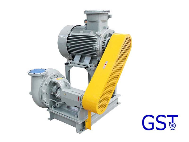
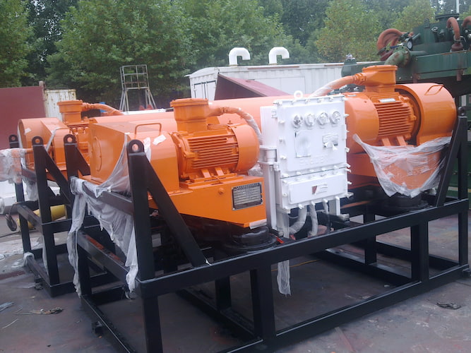
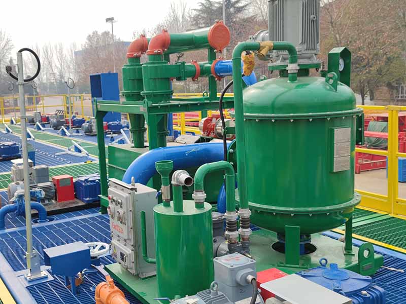
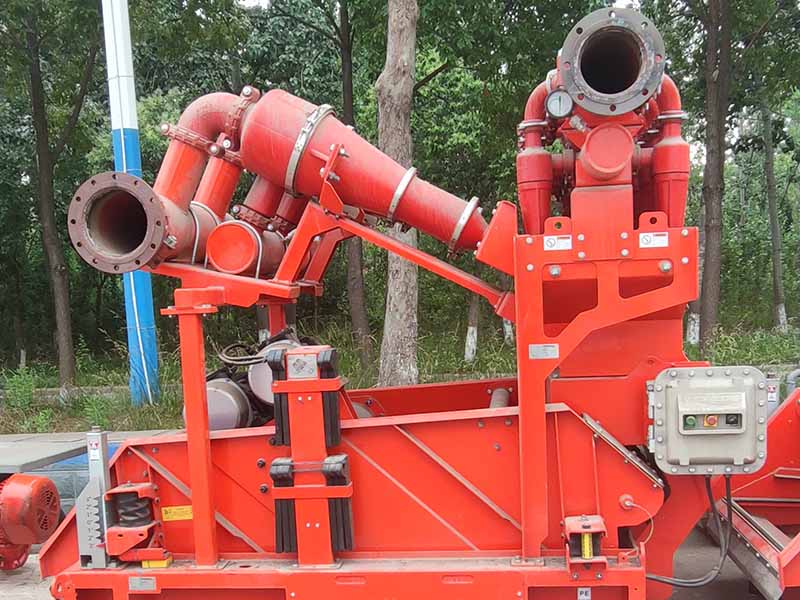
The spray system of the F type drilling mud pump is mainly composed of components such as the spray pump, cooling water tank, and spray pipes. The following is an introduction to the advantages, working process, and pressure control of the spray system.
Ⅰ. The F-type drilling mud pump spray system has the following main advantages:Efficient Cooling
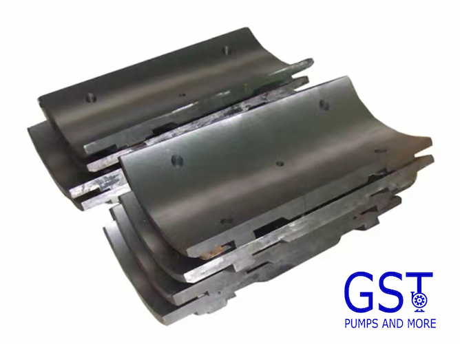
The spray system can accurately spray the cooling liquid onto the key heat-generating parts of the mud pump, such as the mud pump fluid end module and mud pump piston. Through the heat absorption and evaporation of the liquid, it can quickly take away a large amount of heat, effectively reducing the working temperature of these components and ensuring that the mud pump can still maintain stable performance under high-load operation conditions.
Extended Component Lifespan
The stable cooling effect helps to reduce the damage to the Mud pump fluid end module and piston caused by thermal fatigue and wear, thus prolonging their service life. At the same time, proper cooling can prevent the rubber seals from aging and failing due to overheating, maintain good sealing performance, reduce mud leakage, and thus reduce maintenance costs and replacement frequencies.
Improved Mud Pump Efficiency
When the key components are within the appropriate temperature range, the overall operation efficiency of the mud pump is improved. The cooling system can prevent the expansion and deformation of components caused by overheating, ensure the matching accuracy between components, make the power transmission of the mud pump smoother, reduce energy loss, and thus improve its volumetric efficiency and hydraulic efficiency.
Improved Working Environment
During the cooling process of the spray system, the humidity of the surrounding air will increase, which can reduce the dust flying around the mud pump, improve the air quality of the working environment, and be beneficial to the health of the operators. In addition, the lower equipment temperature also reduces the overall temperature of the working area, making the working conditions of the operators more comfortable.
High Reliability
The spray system of the F- type drilling mud pump usually adopts high-quality materials and advanced manufacturing processes, with good corrosion resistance and wear resistance, and can adapt to harsh drilling site environments. At the same time, the system has a simple and reasonable design, with high stability and anti-interference ability, reducing the downtime caused by system failures and improving the continuity and reliability of drilling operations.
Easy Maintenance
The structure of the spray system is relatively simple, and the layout of each component is reasonable, making it convenient for operators to conduct daily inspections, maintenance, and upkeep. For example, components such as nozzles and pipes are easy to disassemble and replace, and it is also relatively convenient to clean the cooling water tank and add water, which helps to reduce maintenance costs and improve maintenance efficiency.
Ⅱ. The working process of the spray system in the F-series drilling mud pump is as follows:
1.Liquid Storage and Supply: The cooling water tank stores a certain amount of cooling liquid, usually clean water or a special coolant. The inlet of the spray pump is connected to the cooling water tank. When the spray system is started, the spray pump begins to work. Using the suction force generated by the rotation of the impeller, it sucks the cooling liquid in the cooling water tank into the pump body.
2.Pressurization and Conveyance: The spray pump pressurizes the sucked cooling liquid to give it sufficient pressure energy. The pressurized cooling liquid is discharged from the outlet of the pump and enters the conveying pipeline.
3.Distribution and Spraying: The high-pressure cooling liquid discharged from the outlet of the spray pump flows along the conveying pipeline. There are multiple branch pipelines set on the conveying pipeline, which respectively lead to various parts of the mud pump that need cooling and flushing, such as the Mud pump fluid end module and piston. A nozzle is installed at the end of each branch pipeline, and the nozzle sprays the cooling liquid onto the surfaces of the Mud pump fluid end module and piston at a certain angle and in a certain manner.
4.Cooling and Flushing: The cooling liquid sprayed onto the surfaces of the Mud pump fluid end module and piston absorbs the heat generated by these components during the working process through heat exchange, reducing their temperature. At the same time, the cooling liquid can also wash away the mud particles and impurities adhering to the surfaces of the Mud pump fluid end module and piston, preventing mud accumulation and caking, and reducing wear and corrosion.
5.Return and Circulation: After completing the cooling and flushing tasks, the cooling liquid, carrying heat and the flushed impurities, flows back to the cooling water tank from various parts of the mud pump. During the return process, part of the cooling liquid may pass through a filtration device to remove larger impurity particles in it and ensure the cleanliness of the cooling liquid. The cooling liquid that returns to the cooling water tank is cooled down through natural cooling or other cooling methods and can be sucked in by the spray pump again for the next round of the cooling cycle.
Ⅲ. The working pressure of the spray system has many impacts on the performance of the F-series drilling mud pump, which are specifically as follows:
Cooling Effect
Low Pressure: The cooling liquid cannot fully cover the surfaces of key components such as the Mud pump fluid end module and piston, resulting in uneven cooling, excessive local temperature, accelerated component wear, and reduced service life of the mud pump. In addition, a lower pressure will slow down the flow rate of the cooling liquid, reduce the heat exchange efficiency, and fail to take away the heat generated by the components in a timely manner, affecting the normal operation of the mud pump.
High Pressure: Although it can enhance the cooling effect, it may cause serious splashing of the cooling liquid, not only causing waste but also possibly affecting the working environment. At the same time, too high a pressure will increase the load on the components of the spray system, such as nozzles and pipes, and is likely to cause damage to these components, affecting the reliability of the system.
Component Wear
Low Pressure: Insufficient cooling will increase the friction between the Mud pump fluid end module and the piston because high temperature will change the performance of the component materials, reduce the surface hardness, and make it more prone to wear. In addition, the viscosity of the mud increases at high temperatures, which will also increase the frictional resistance of the components, further aggravating the wear and affecting the performance and service life of the mud pump.
High Pressure: It may cause excessive scouring of the surfaces of the Mud pump fluid end module and piston, especially in the area near the nozzle. Over time, it will cause the gradual loss of materials in these parts, reducing the dimensional accuracy of the components and affecting the sealing performance and volumetric efficiency of the mud pump.
Sealing Performance
Low Pressure: Due to insufficient cooling, the seals are prone to aging and deformation due to overheating, losing their good sealing performance and resulting in mud leakage. Mud leakage will not only cause environmental pollution but also affect the normal operation of the mud pump and reduce its working efficiency.
High Pressure: It may exert additional pressure on the seals, increasing the stress borne by the seals. Once it exceeds the bearing range of the seals, it will accelerate the damage of the seals, also resulting in mud leakage and affecting the performance and reliability of the mud pump.
System Stability
Low Pressure: The spray system cannot function properly, and the key components of the mud pump are in a high-temperature state, which may trigger a series of failures, such as component deformation and jamming, affecting the stability of the mud pump, and even leading to shutdown accidents, affecting the smooth progress of drilling operations.
High Pressure: It will make the components of the spray system itself bear a relatively large pressure. For example, the pipeline may burst due to excessive pressure, and the motor of the spray pump may also malfunction due to excessive load. These will reduce the stability of the entire system, increase maintenance costs, and lead to longer downtime.
Ⅳ. The adjustment and control of the working pressure of the spray system of the F-series drilling mud pump are usually achieved through the following methods:
Pressure Regulating Valve
Installation Location: It is generally installed on the outlet pipeline of the spray pump. By adjusting the opening degree of the valve, the flow rate of the fluid can be controlled, and thus the system pressure can be adjusted.
Working Principle: When it is necessary to increase the pressure, the valve opening is adjusted to be smaller, reducing the flow area of the fluid and increasing the fluid pressure in the pipeline. Conversely, by increasing the valve opening, the pressure can be reduced. The pressure regulating valve can be manually adjusted according to actual needs, or an automatic regulating valve can be used, which automatically adjusts the valve opening according to the preset pressure value.
Mud Pump Relief Valve
Function: It is mainly used to limit the maximum pressure of the system and play a role in safety protection. When the system pressure exceeds the set pressure of the relief valve, the relief valve opens, and part of the fluid flows back to the cooling water tank, thus preventing the system pressure from being too high and damaging the equipment.
Setting Method: According to the design pressure of the spray system and the working requirements of the mud pump, the opening pressure of the relief valve should be set reasonably. Usually, the set pressure of the relief valve should be slightly higher than the normal working pressure to ensure that the system will not overflow during normal operation, but it can play a protective role in a timely manner when the pressure rises abnormally.
Variable Frequency Speed Regulation Device
Application Principle: By changing the power supply frequency of the motor of the spray pump, the rotation speed of the motor can be adjusted, and thus the flow rate and pressure of the spray pump can be changed. When it is necessary to reduce the pressure, the rotation speed of the motor is decreased, reducing the output flow rate of the pump and the pressure will decrease accordingly. When it is necessary to increase the pressure, the rotation speed of the motor is increased.
Advantages: This method can achieve continuous and precise adjustment of the pressure, and can adjust the pressure in real time according to the actual working conditions of the mud pump, with high flexibility and energy-saving effects.
Pressure Sensor and Control System
Feedback Control: A pressure sensor is installed on the pipeline of the spray system to monitor the pressure value of the system in real time and transmit the pressure signal to the control system. The control system compares the preset pressure value with the actually monitored pressure value and then sends out corresponding control signals to automatically adjust the pressure regulating valve or the variable frequency speed regulation device, keeping the system pressure within the set range.Advantages: This automated pressure control method can quickly and accurately respond to changes in the system pressure, improve the accuracy and stability of pressure control, reduce manual intervention, and lower the risk of operational errors.
When adjusting and controlling the working pressure of the spray system, it is necessary to comprehensively consider the specific model of the F-series drilling mud pump, working conditions, and the design requirements of the spray system. At the same time, regularly inspect and maintain the pressure regulating devices to ensure their normal operation, so as to ensure that the spray system can stably provide the appropriate cooling and flushing pressure for the mud pump.
Read More


 Language :
 English
 Русский
 عربي
عربي
 GET A QUOTE


 IPv6 network supported