facebook linkedin youtube
National Unified Hotline :

+86 22 5807 5652

Email Us :

gm@geostarpe.com

#Language :

EnglishEnglish

内页banner

Search

Home

Sand Pump Shaft

  • What is cavitation in a mud centrifugal pump?
    What is cavitation in a mud centrifugal pump?
    Mar 21, 2025
    The cavitation of the mud centrifugal pump in oil drilling refers to the phenomenon that during the oil drilling process, when the local pressure inside the mud centrifugal pump is lower than the saturation vapor pressure of the mud at the current temperature, the water in the mud vaporizes to form bubbles. These bubbles quickly condense and burst when they flow with the mud to the high-pressure area, resulting in a series of harmful effects. Ⅰ. Causes of Cavitation Installation aspects: If the installation height of the pump is too high, the pressure at the pump inlet will decrease. When it is lower than the saturation vapor pressure of the mud, cavitation is likely to occur; if the resistance of the suction pipeline is too large, such as a long and slender pipeline, many bends, a small diameter, or blockage, it will lead to a decrease in the inlet pressure and trigger cavitation. Operation parameter aspects: If the flow rate is too large, exceeding the designed flow rate of the pump, the flow velocity at the impeller inlet will increase, and the pressure will decrease, increasing the possibility of cavitation; if the mud temperature is too high, the saturation vapor pressure of the mud will increase, and it is more likely to reach the saturation vapor pressure and vaporize under the same pressure conditions. Mud property aspects: The properties of the mud, such as density, viscosity, and gas content, affect the occurrence of cavitation. For example, mud with a high gas content is likely to form bubbles inside the pump, increasing the risk of cavitation; too high viscosity will make it difficult for the mud to be sucked in, resulting in a decrease in the inlet pressure. Ⅱ. The cavitation of the mud centrifugal pump can be judged from the following aspects: Sound judgment Noise generation: When cavitation occurs, due to the formation, development, and bursting of bubbles, irregular noise will be generated, and the sound will increase with the aggravation of the cavitation degree. This noise is significantly different from the normal operation sound, and it can be initially judged whether there is cavitation by listening carefully. Abnormal vibration: Cavitation will cause the vibration of the pump body because the impact force generated by the bursting of bubbles will make components such as the impeller and the pump casing subject to uneven forces. By touching the pump body or using a vibration monitoring instrument, it can be found that the vibration amplitude of the pump increases significantly, and the vibration frequency will also change. Compared with the stable state during normal operation, the vibration during cavitation is more intense, and sometimes the entire pump device can even be felt shaking. Performance change judgment Flow rate decrease: Cavitation will cause the fluid flow inside the pump to be obstructed. The bubbles occupy a certain space, reducing the effective flow area of the mud, thus resulting in a decrease in the flow rate. If it is found that the actual flow rate of the pump is significantly lower than the rated flow rate, and other possible causes, such as pipeline blockage and the valve not being fully open, have been excluded, the possibility of cavitation needs to be considered. Head decrease: Cavitation will damage the normal working state of the impeller, reducing the impeller's ability to do work on the mud, and thus leading to a decrease in the head. When the outlet pressure of the pump is significantly lower than the normal operating pressure and the head cannot meet the system requirements, cavitation may be one of the reasons. Efficiency decrease: During the cavitation process, due to the formation and bursting of bubbles, energy will be consumed. At the same time, the flow state of the fluid becomes disordered, resulting in a decrease in the overall efficiency of the pump. If it is found that the energy consumption of the pump increases, but the output flow rate and head do not increase accordingly, or even decrease, it is very likely that cavitation has occurred. Appearance inspection judgment Impeller surface damage: Regularly disassemble the pump for inspection. If there are pits, honeycomb-like depressions, or wear marks on the impeller surface, especially at the inlet and leading edge of the blades, it is likely caused by cavitation. With the development of cavitation, these damages will gradually expand, and in severe cases, it may even lead to the perforation or fracture of the impeller blades. Inner wall damage of the pump casing: When inspecting the inner wall of the pump casing, if there are similar cavitation marks, such as local wear, scratches, or small-area peeling, it also indicates that there may be a cavitation problem with the pump. Especially in the area near the impeller outlet and the volute tongue, due to the large pressure change here, cavitation damage is more likely to occur. In addition, it can also be judged by observing the vacuum gauge installed at the pump inlet and the pressure gauge at the outlet. If the reading of the vacuum gauge increases abnormally, and at the same time, the reading of the pressure gauge decreases abnormally, this may also be a sign of cavitation, because cavitation will lead to a decrease in the pressure at the pump inlet and unstable pressure at the outlet. Ⅲ. Cavitation has a significant impact on the service life of the mud centrifugal pump, mainly reflected in the following aspects: Centrifugal pump impeller damage: When cavitation occurs, the bubbles burst near the impeller surface, and the generated impact force will continuously erode the impeller. In the initial stage, pits will appear on the impeller surface. As cavitation intensifies, the pits gradually expand and connect into honeycomb-like depressions, causing the material on the impeller surface to fall off, resulting in the thinning, perforation, or even fracture of the impeller blades, seriously damaging the structural integrity and hydraulic performance of the impeller, and greatly shortening the service life of the impeller. An impeller that could originally be used for several years may need to be replaced within a few months or even a shorter time due to severe cavitation. Centrifugal pump casing wear: The bubbles generated by cavitation will also burst inside the pump casing, causing impact and erosion on the inner wall of the pump casing, resulting in wear, scratches, and depressions on the inner surface of the pump casing, reducing the strength and wear resistance of the pump casing. Under the long-term effect of cavitation, cracks may appear in the pump casing, affecting its sealing performance and pressure-bearing capacity, and thus shortening the service life of the pump casing, which requires early repair or replacement. Pump shaft failure: The vibration and unstable fluid flow caused by cavitation will make the pump shafts bear additional loads and alternating stresses. This will accelerate the wear of the shafts, leading to an increase in the clearance of the shafts and a decrease in precision, and then triggering faults such as shaft heating and seizure, greatly shortening the service life of the shafts. The original normal service cycle may be several years, but under the influence of cavitation, the bearings may need to be replaced in less than a year. Seal damage: The vibration and pressure fluctuations caused by cavitation will affect the sealing performance of the pump, subjecting the seals to additional impacts and wear. For mechanical seals, it may lead to increased wear and deformation of the sealing surface, losing the sealing effect and causing mud leakage; for packing seals, it will accelerate the wear of the packing, and frequent adjustment and replacement of the packing are required. The damage of the seals not only affects the normal operation of the pump but may also lead to the leakage of the medium, polluting the environment, and increasing the maintenance cost and downtime, indirectly affecting the overall service life of the mud centrifugal pump. In conclusion, cavitation will damage the key components of the mud centrifugal pump from multiple aspects, significantly shortening its service life, increasing the maintenance cost and equipment replacement frequency. Therefore, during the use of the mud centrifugal pump, the cavitation problem must be taken seriously and effective preventive measures should be taken. Ⅳ. In order to reduce the cavitation of the mud centrifugal pump in oil drilling, measures can also be taken from aspects such as optimizing equipment design and selection, improving installation conditions, optimizing operation, and strengthening maintenance management. The specific introductions are as follows: Optimizing design and selection Reasonable pump type selection: According to the characteristics of the oil drilling mud, including parameters such as flow rate, head, density, and viscosity, select a suitable centrifugal pump model. Ensure that the performance curve of the selected pump matches the actual working conditions, so that the pump operates in the high-efficiency area and avoids working under conditions deviating from the designed working conditions to reduce the occurrence of cavitation. Adopting anti-cavitation design: Select impellers with anti-cavitation performance design, such as using double-suction impellers, which can make the flow velocity distribution at the impeller inlet more uniform, reduce the local pressure drop, and reduce the possibility of cavitation. In addition, optimizing the blade shape and the position of the inlet edge of the impeller can also improve the flow situation of the fluid inside the impeller and enhance the anti-cavitation ability of the pump. Improving installation conditions Controlling the installation height: According to the allowable cavitation margin of the pump and the actual on-site situation, accurately calculate the installation height of the pump. The installation height should ensure that the pressure at the pump inlet is higher than the saturation vapor pressure of the mud at the working temperature to prevent the formation of bubbles. Usually, the lower the installation height, the more conducive it is to avoiding cavitation, but the on-site space layout and operation convenience also need to be considered. Optimizing the suction pipeline: Try to shorten the length of the suction pipeline, reduce unnecessary bends, valves, and other pipe fittings to reduce the pipeline resistance. At the same time, select an appropriate pipe diameter to ensure that the flow velocity of the mud in the suction pipeline is moderate, generally, it is recommended that the flow velocity be controlled between 1.5 - 2.5m/s. In addition, ensure the sealing performance of the suction pipeline to prevent air from leaking into the pipeline and avoid cavitation caused by air accumulation. Optimizing operation Stabilizing operation parameters: Keep the operation parameters of the pump, such as flow rate and head, stable, and avoid large fluctuations. Through reasonable adjustment of the outlet valve or the use of variable frequency speed regulation and other methods, make the pump operate near the designed working conditions. Avoid long-term operation under extreme working conditions such as small flow rate and high head or large flow rate and low head to prevent uneven pressure distribution inside the pump and the occurrence of cavitation. Controlling the mud temperature: Too high a mud temperature will increase the saturation vapor pressure of the mud and increase the risk of cavitation. Therefore, effective cooling measures should be taken, such as setting up a mud cooler or using circulating cooling water and other methods to control the mud temperature within a reasonable range, generally, it is recommended that the mud temperature does not exceed 60℃. Reducing the gas content of the mud: Too high a gas content in the mud will promote the occurrence of cavitation. Before the mud enters the pump, a degassing device can be used to pre-treat the mud to reduce its gas content. At the same time, pay attention to avoiding the formation of vortices in the mud tank to prevent air from being drawn into the mud. Strengthening maintenance management Regular inspection and maintenance: Regularly inspect the mud centrifugal pump, including the wear conditions of components such as the impeller, pump casing, and seals, and timely find and replace damaged or severely worn components. Check the pump's bearings, lubrication system, and cooling system, etc., to ensure their normal operation, so as to ensure the overall performance of the pump and reduce the impact of cavitation. Cleaning and maintenance: Keep the pump body and the suction pipeline clean, regularly clean the filter and impurities to prevent blockage and ensure that the mud can flow smoothly into the pump. At the same time, carry out appropriate maintenance on the pump, such as regularly adding lubricating oil and replacing seals, etc., which helps to improve the operation efficiency and reliability of the pump and reduce the probability of cavitation occurrence.    
    Read More
  • What is the sand pump shaft?
    What is the sand pump shaft?
    Mar 19, 2025
    The sand pump shaft is one of the key components of the sand pump. The following is a detailed introduction from various aspects:
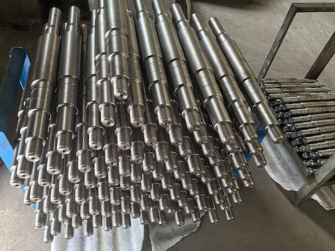
 Ⅰ. Sand Pump Shaft Structural Features 
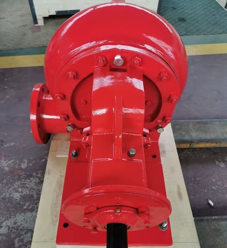
The sand pump shaft is usually in the form of a slender cylindrical structure, with both ends connected to the sand pump impeller and the driving device (such as an electric motor) respectively. Generally, there are shaft shoulders for installing the impeller, keyways for fixing the impeller, and parts for installing bearings on the shaft. Some sand pump shafts may also have seal journals for installing mechanical seals or packing seals to prevent the leakage of the medium. Functions Power Transmission: Transmit the rotational power of the driving device such as the electric motor to the impeller, making the impeller rotate at a high speed, thus realizing the transportation of media such as mortar. Impeller Support: Provide stable support for the impeller, ensure the accurate central position of the impeller during the rotation process, and prevent the impeller from rubbing or colliding with the sand pump casing. Load Bearing: Bear the radial force, axial force from the impeller, and vibration loads caused by factors such as uneven medium flow. Material Selection Common Carbon Steel: Such as Q235, etc., which has certain strength and toughness and a relatively low cost. However, it is relatively poor in wear resistance and corrosion resistance, and is suitable for occasions where the sand content of the conveyed medium is low and the corrosiveness is not strong. Alloy Steel: Such as 40Cr, 35CrMo, etc., which has high strength, hardness, and wear resistance, as well as good toughness. It can withstand large loads and wear, and is suitable for conveying media with high sand content and large particle hardness. Stainless Steel: Such as 304, 316L, etc., which has good corrosion resistance and certain wear resistance. It is widely used in sand pumps in some environments with corrosive media, such as the chemical industry and electroplating industry. Special Alloys: For some special working conditions, such as high temperature, high pressure, and strong corrosion environments, some special alloy materials, such as nickel-based alloys and titanium alloys, will also be used to meet the requirements of the sand pump shaft under extreme conditions. Technical Requirements 
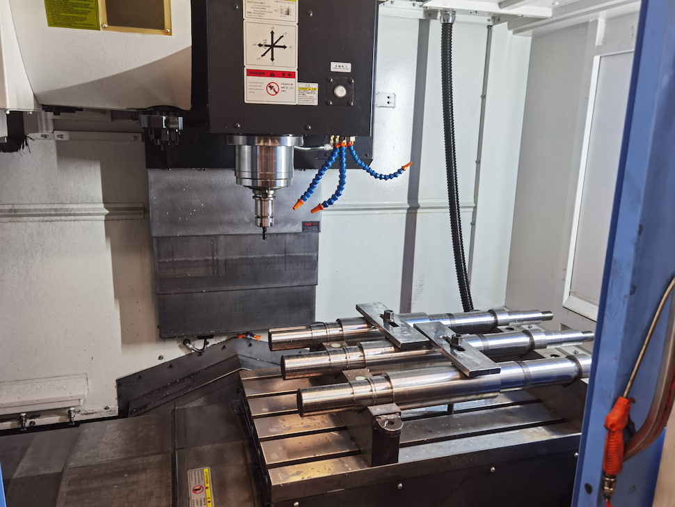
Dimensional Accuracy: The dimensional accuracy of each part of the sand pump shaft is required to be high, such as the tolerance of the shaft diameter, roundness, and coaxiality, etc., to ensure the fitting accuracy with components such as the impeller and bearings, and ensure the normal operation of the pump. Surface Roughness: The surface roughness of the shaft directly affects the friction loss and sealing performance with other components. Generally, the surface roughness of the shaft journal and the sealing part is required to be low to reduce wear and leakage. Hardness Requirements: According to different materials and working conditions, the sand pump shaft needs to meet certain hardness requirements to improve its wear resistance and fatigue resistance. For example, for the sand pump shaft conveying high-hardness sand particles, its hardness is usually required to be around HRC40 - 50. Straightness: The straightness of the shaft should be controlled within a certain range. Otherwise, problems such as impeller eccentricity and uneven bearing force will occur, affecting the performance and service life of the pump. Maintenance Points Regular Inspection: Regularly check the wear condition of the sand pump shaft, especially in the easily worn places such as the impeller installation part, the bearing part, and the sealing part. It can be checked by measuring the shaft diameter and observing the surface wear marks. Lubrication Maintenance: Ensure good lubrication of the bearing and other parts, and add or replace the lubricating grease or lubricating oil according to the specified cycle and requirements. Good lubrication can reduce friction, and reduce the wear and heating of the shaft. Seal Maintenance: Check whether the sealing device is in good condition, and deal with any leakage in time. Prevent the medium leakage from corroding and wearing the shaft, and at the same time avoid environmental pollution and material loss caused by the leakage. Overload Prevention: During the use process, avoid the overload operation of the sand pump to prevent the shaft from bearing excessive loads, resulting in the deformation or damage of the shaft. Storage Requirements: If the sand pump shaft needs to be stored for a long time, anti-rust measures should be taken, such as applying anti-rust oil, wrapping moisture-proof materials, etc., and it should be placed in a dry and ventilated place to prevent the shaft from rusting and deforming. The requirements for the sand pump shaft may vary in different application scenarios. When selecting a high-quality sand pump shaft, it is necessary to comprehensively consider specific working conditions, medium characteristics, conveying requirements, and other factors to ensure the stable operation and efficient work of the sand pump. Ⅱ. Selecting a sand pump shaft suitable for a specific application scenario requires considering multiple factors. The following are some key points: 1.Medium Characteristics Particle Size and Hardness: If the conveyed medium contains large and hard sand particles, such as quartz sand, etc., a material with good wear resistance, such as cemented carbide or an alloy steel shaft with a specially hardened surface treatment, should be selected to resist the erosion and wear of the sand particles. Corrosiveness: When the medium is corrosive, such as in some chemical industries or seawater environments, a corrosion-resistant material, such as a stainless steel shaft, should be selected, or the surface of the shaft should be subjected to anti-corrosion treatment, such as nickel plating, chrome plating, or spraying an anti-corrosion coating. Concentration: When the sand particle concentration in the medium is high, it will increase the wear degree of the shaft. The shaft needs to have better wear resistance and strength, and a shaft with a larger diameter and better material can be selected to bear a greater load. 2.Working Conditions Temperature: For sand pumps working in high-temperature environments, the material of the shaft should have good thermal stability and be able to withstand high temperatures without deformation or performance degradation. For example, in geothermal development or some high-temperature industrial processes, a special alloy shaft with high temperature resistance may be required. Pressure: For sand pumps operating under high pressure, the shaft needs to have sufficient strength and stiffness to withstand the pressure and prevent bending or fracture. Usually, high-strength alloy steel will be selected, and the structural design and dimensions of the shaft will be optimized according to the magnitude of the pressure. Rotation Speed: When the rotation speed of the sand pump is high, the shaft will be subjected to a large centrifugal force and vibration. This requires the shaft to have good dynamic balance performance and fatigue resistance. The requirements can be met by improving the manufacturing accuracy of the shaft, conducting dynamic balance tests, and selecting appropriate materials. 
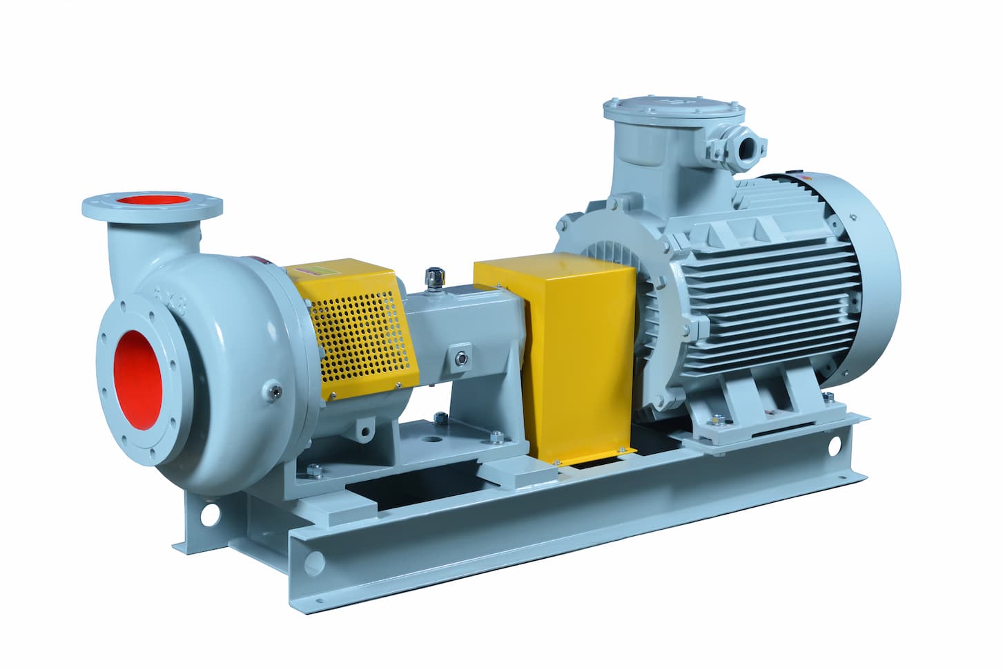
3.Pump Type and Specification Pump Type: Different types of sand pumps, such as centrifugal sand pumps and plunger sand pumps, have different requirements for the shaft. The shaft of a centrifugal sand pump mainly bears radial force and torque, while the shaft of a plunger sand pump also needs to bear a large axial force. Therefore, when selecting the premium quality sand pump shaft, the force characteristics of the shaft should be considered according to the type of the pump. Pump Specification: Large-specification sand pumps usually require a shaft with a larger diameter and higher strength to transmit power and support the impeller. According to the parameters of the pump such as power, flow rate, and head, the minimum diameter of the shaft and the required strength grade can be determined. 4.Installation and Maintenance Requirements Installation Method: The structural design of the shaft should be convenient for installation and disassembly. For example, a reasonable connection method such as a shaft shoulder, keyway, or spline should be adopted to facilitate the assembly of components such as the impeller and bearings. At the same time, the limitations of the installation space should be considered, and the appropriate length and external dimensions of the shaft should be selected. Maintenance Convenience: Select a shaft that is easy to maintain, such as a shaft with a simple surface treatment process and good repairability. In addition, the lubrication and sealing methods of the shaft should also be considered to ensure that maintenance and upkeep can be carried out conveniently during the operation process, reducing downtime. 5.Cost and Reliability Cost: On the premise of meeting the requirements of the application scenario, cost factors should be comprehensively considered. The prices of sand pump shafts with different materials and manufacturing processes vary greatly, and suitable products should be selected according to the project budget. However, the quality and reliability of the shaft should not be sacrificed just to reduce costs. Otherwise, it may lead to frequent repairs and replacements, increasing the overall cost. Reliability: Select brands and suppliers with a good reputation and quality assurance to ensure the reliability and stability of the sand pump shaft. The usage experience and evaluations of other users can be referred to, or the supplier can be required to provide relevant test reports and quality certifications. In conclusion, selecting a sand pump shaft suitable for a specific application scenario requires comprehensively considering multiple factors such as medium characteristics, working conditions, pump type and specification, installation and maintenance requirements, as well as cost and reliability. Through the analysis and trade-off of these factors, the most suitable sand pump shaft can be selected to ensure that the sand pump can operate stably and efficiently for a long time in a specific application scenario. Ⅲ. Various faults may occur during the use of the sand pump shaft. The following are some common faults and their causes: Wear Wear at the Fitting Part between the Impeller and the Shaft: Usually, it is caused by the insecure installation of the impeller on the shaft, which causes a slight displacement during operation, or the sand particles in the medium enter the fitting gap, resulting in friction and wear, causing the shaft diameter to become smaller, affecting the normal operation of the impeller and the performance of the pump. Shaft Journal Wear: The shaft journal is the part that fits with the bearing. During long-term operation, due to reasons such as poor lubrication, improper bearing installation, and shaft vibration, the surface of the shaft journal will be worn, destroying the fitting accuracy between the shaft and the bearing, causing the bearing to heat up, the vibration to intensify, and even damaging the bearing. Shaft Surface Wear: When the sand pump conveys the sand-containing medium, the surface of the shaft is directly in contact with the medium. The erosion of the sand particles will gradually wear the surface of the shaft, reducing the strength and wear resistance of the shaft. In severe cases, it may lead to the fracture of the shaft. Corrosion Chemical Corrosion: When the medium conveyed by the sand pump is corrosive, such as acid, alkali, salt, and other solutions, the material of the shaft will chemically react with the medium, resulting in the corrosion of the shaft surface, and the appearance of corrosion marks such as rust spots and pitting, reducing the surface quality and strength of the shaft. Deformation Bending Deformation: It may be caused by the improper adjustment of the concentricity of the shaft during the installation of the sand pump, or by the uneven external force during the operation process, such as the imbalance of the impeller, the stress transfer of the pipeline, etc., resulting in the bending deformation of the shaft. The bending of the shaft will cause the impeller to rub against the pump casing, increasing the vibration and noise, and also affecting the service life of the bearing. Torsional Deformation: When the sand pump is starting or stopping, or encountering sudden load changes, the shaft will bear a large torque. If the torque exceeds the bearing capacity of the shaft, torsional deformation may occur. In addition, motor faults, transmission system faults, etc. may also cause the shaft to bear abnormal torque, resulting in torsional deformation. Fracture Fatigue Fracture: The sand pump shaft will generate fatigue cracks under the long-term action of alternating stress. These cracks will gradually expand, and when the cracks expand to a certain extent, the shaft will fracture. Fatigue fracture usually occurs at the stress concentration parts of the shaft, such as the shaft shoulder, keyway, thread, etc. Overload Fracture: If the sand pump encounters unexpected overload situations during operation, such as a sudden increase in the viscosity of the medium, the impeller being stuck by foreign objects, etc., the load borne by the shaft exceeds its ultimate strength, and overload fracture will occur. This kind of fracture usually occurs suddenly without obvious signs. The faults of the sand pump shaft will affect the normal operation of the sand pump. Therefore, it is necessary to regularly inspect and maintain the sand pump shaft, discover and deal with potential problems in a timely manner, so as to extend the service life of the sand pump shaft and ensure the reliable operation of the sand pump. Ⅳ. The dynamic balance accuracy of the sand pump shaft has multiple important impacts on the performance of the pump, as follows: Vibration and Noise When the dynamic balance accuracy is high, the vibration generated when the sand pump shaft rotates is small. Because good dynamic balance means that the mass distribution of each part of the shaft is uniform, and the resultant centrifugal force during rotation is close to zero, and no large periodic exciting force will be generated. This helps to reduce the overall vibration of the pump, lower the noise level, make the pump run more smoothly and quietly, reduce the noise pollution to the surrounding environment, and is also beneficial to extending the service life of the pump and its auxiliary equipment.If the dynamic balance accuracy is poor, the shaft will generate a large centrifugal force due to uneven mass distribution during rotation, thus causing strong vibration and noise. This vibration will not only affect the working environment of the operators but also may cause the loosening of the pump components, increased wear, and even trigger equipment failures. Bearing Wear The sand pump shaft with high dynamic balance accuracy can make the bearing load uniform. Due to the stable rotation of the shaft, the radial force and axial force acting on the bearing are relatively stable and within the design range, and the contact stress between the balls or rollers and the raceway of the bearing is uniform, so the wear is also uniform and slow, which can effectively extend the service life of the bearing, reduce the maintenance cost and downtime. When the dynamic balance accuracy is insufficient, the vibration of the shaft will make the bearing bear additional alternating loads, resulting in uneven wear between the balls or rollers and the raceway inside the bearing, shortening the service life of the bearing, and increasing the frequency of bearing replacement and maintenance workload. Impeller Wear When the dynamic balance accuracy of the sand pump shaft is high, the impeller can maintain the correct rotation posture and position under the drive of the stable shaft, the gap between the impeller and the pump casing is uniform, and the flow of the medium such as mortar around the impeller is also relatively stable. The wear of the impeller is relatively uniform, and the local wear will not be aggravated due to the vibration of the shaft, thus extending the service life of the impeller and ensuring the conveying efficiency of the pump. The shaft with poor dynamic balance will make the impeller swing during rotation, resulting in changes in the gap between the impeller and the pump casing, turbulent flow of the medium, and the impeller will be subjected to greater impact and wear locally, thereby affecting the performance of the impeller, reducing the head and flow rate of the pump, and increasing energy consumption. Pump Efficiency The high dynamic balance accuracy of the sand pump shaft helps to improve the efficiency of the pump. Because the stable rotation of the shaft enables the impeller to efficiently transmit mechanical energy to the medium, reducing the efficiency reduction caused by vibration and energy loss. The flow of the medium in the pump is smoother, and the hydraulic loss is reduced, so that the pump can output more flow rate and head under the same input power, improving the overall efficiency of the pump. Poor dynamic balance accuracy will make the pump consume more energy to overcome vibration and unstable factors during operation, resulting in increased energy loss and reduced pump efficiency. This will not only increase the energy consumption cost but also may affect the efficiency and economy of the entire process flow.    
    Read More
  • What is a Mud Pump Centrifugal Super Charging Pump?
    What is a Mud Pump Centrifugal Super Charging Pump?
    Mar 11, 2025
    The mud pump centrifugal super charging pump is an important device in the mud pump system. The following is a detailed introduction to it: Ⅰ. Definition and Function Basic Definition: The mud pump centrifugal super charging pump is usually a small auxiliary pump connected to the suction line of the mud pump. Its main function is to create a vacuum by discharging air and filling the pump with drilling fluid. This pre-fills the mud pump, enabling it to operate efficiently and provides the required pressure for the circulation of the drilling mud. Working Principle: It operates based on the principle of centrifugal force. The impeller rotates at a high speed, generating centrifugal force that causes the drilling mud to move from the center of the impeller to the edge. This movement creates a pressure difference, with low pressure at the impeller inlet and high pressure at the outlet. Therefore, the mud is sucked in from the suction port and discharged from the outlet under pressure, realizing the transportation of the drilling mud. Ⅱ. Main Components Centrifugal Pump Impeller: Semi-closed impellers or closed impellers are usually used. The semi-closed impeller is suitable for transporting mud containing certain particles, which can reduce the wear of the particles on the impeller and has good passageability; the closed impeller can better improve the efficiency and head of the pump and is suitable for occasions with high requirements for mud transportation. Pump Casing: It is generally made of wear-resistant materials, such as high chromium alloy, wear-resistant cast iron, etc., to withstand the erosion and wear of the mud. The shape of the pump casing is designed as a spiral flow channel, allowing the mud to gradually decelerate in the pump casing and convert the kinetic energy into pressure energy to achieve the pressurization of the mud. Shaft Seal: To prevent mud leakage and air from entering the pump, the shaft seal device is crucial. Common shaft seals include mechanical seals and packing seals. Mechanical seals have the advantages of good sealing performance, small leakage, and long service life; packing seals have the characteristics of simple structure, low cost, and convenient maintenance. Bearings: They are used to support the pump shaft and ensure the rotation accuracy and stability of the pump shaft. Since the mud pump centrifugal super charging pump may bear large radial and axial forces during operation, the bearings usually need to have high load-bearing capacity and wear resistance. Ⅲ. Structural Features Wear-resistant Materials: Due to the abrasiveness of the drilling mud, the components of the pump in contact with the mud, such as the impeller and the pump casing, are usually made of wear-resistant materials such as high chromium alloy and wear-resistant ductile iron. This enhances the wear resistance of the pump and prolongs its service life. Grease Lubrication: The bearings of the pump are usually lubricated with grease. This lubrication method can reduce the friction and wear between the bearing and the shaft, ensuring the smooth operation of the pump and is suitable for the working conditions where the pump needs to operate continuously for a long time. Ⅳ. Advantages In terms of Structure and Installation Simple and Compact Structure: The mud pump centrifugal super charging pump is usually composed of main components such as the pump body, impeller, and shaft. The overall structure is relatively simple, without complex transmission devices or multi-chamber structures. Easy Installation: It adopts a pipeline structure design, with the inlet and outlet on the same straight line. During installation, only the inlet and outlet need to be docked. It can be directly installed in series like a pipeline, occupying a small floor space. In terms of Performance and Operation High Efficiency: With an advanced impeller design and optimized internal structure, it can efficiently convert the mechanical energy of the motor into the pressure energy and kinetic energy of the mud, maintaining a high working efficiency under rated working conditions. Stable Operation: The absolute concentricity of the pump shaft and the excellent dynamic and static balance of the impeller ensure that the pump has small vibration and low noise during operation. For example, when the mud pump is running, it will not produce large vibrations and noises, providing a good working environment. Convenient Flow Regulation: The flow is directly proportional to the rotational speed, and the flow can be easily adjusted through a speed change mechanism or a speed-regulating motor, enabling flexible adjustment of the mud transportation volume according to the actual working conditions. Strong Self-priming Ability: Generally, it has a certain self-priming ability. Before starting, there is no need for a large amount of priming operations like some other types of pumps. It can quickly discharge the air in the suction pipe and realize the smooth suction of the mud. In terms of Maintenance and Operation Simple Operation: The operation is relatively simple, and the starting and stopping processes are relatively convenient, without complex operation procedures and professional skills. And it does not require frequent monitoring and adjustment during operation, making it easy to achieve automation and remote operation. Low Maintenance Cost: The simple structure makes the maintenance and repair work relatively easy, and the replacement of parts is also relatively convenient. For example, when replacing the vulnerable parts such as the impeller and seal of the mud pump during maintenance, there is no need to disassemble a large number of parts, reducing the maintenance cost and repair time. Ⅴ. When choosing a suitable model of the mud pump centrifugal super charging pump, multiple factors need to be comprehensively considered. The following are the specific key points:Medium Characteristics Viscosity: High viscosity of the mud will affect the performance and efficiency of the pump, reducing the head and flow of the pump. For mud with a viscosity greater than 500mPa・s, a centrifugal super charging pump with a large passage impeller and low rotational speed is advisable to reduce the flow resistance and prevent blockage. Solids Content: Mud with a high solids content is highly abrasive to the pump. When the sand content is below 15%, a pump made of ordinary cast iron material can be used; when the sand content is between 15% and 40%, wear-resistant materials such as high chromium alloy are required; when the sand content exceeds 40%, a pump made of duplex stainless steel or with a tungsten carbide coating on the surface should be considered. Corrosiveness: If the mud is corrosive, such as containing acids, alkalis, and other chemical substances, a pump made of corrosion-resistant materials, such as rubber-lined, plastic-lined, titanium alloy, etc., should be selected to extend the service life of the pump. Flow and Head Requirements Flow: Determine the required mud transportation flow according to the actual engineering needs, generally in cubic meters per hour (m³/h). For example, in large-scale mining operations, a flow of hundreds of cubic meters per hour may be required. The rated flow of the selected pump should be slightly larger than the actual required flow to ensure that the transportation requirements can be met under different working conditions. Head: The head refers to the height that the pump can lift the mud, in meters (m). The required head needs to be calculated according to factors such as the transportation distance, height difference, and pipeline resistance. For example, when transporting mud from the underground to the ground, if the vertical height is 100 meters, and considering the pipeline friction and other losses, a pump with a head of 120-150 meters may need to be selected. Working Environment Space Limitation: If the installation space is limited, such as in some underground operations or small sewage treatment plants, a vertical mud pump centrifugal super charging pump can be selected, which occupies a small floor space; in an open space, such as the open-air operation area of a large mine, a horizontal pump is more convenient for installation and maintenance. Temperature and Humidity: In a high-temperature environment, the materials and seals of the pump need to have high-temperature resistance; in a humid or corrosive gas environment, the moisture-proof and anti-corrosion performance of the electrical equipment of the pump should be considered. Power and Control Power Source: There are power-driven and diesel-driven methods. Power-driven is suitable for places with a stable power grid power supply, with the advantages of low operating cost and high efficiency; diesel-driven is suitable for field or remote areas without power grid coverage, such as field geological exploration operations. Control Mode: Select a pump with manual control, automatic control, or remote control according to actual needs. Automatic control and remote control can realize real-time monitoring and adjustment of the operating status of the pump, improving work efficiency and automation level, and are suitable for large-scale engineering projects or unattended places. Other Factors Maintenance Cost: It includes the replacement cost of vulnerable parts, the difficulty of maintenance, etc. Selecting a pump with a simple structure and strong universality of vulnerable parts can reduce the maintenance cost and difficulty, shorten the maintenance time, and improve the operating efficiency of the equipment. Ⅵ. Maintenance of the Mud Pump Centrifugal Charging Pump 1.Daily Maintenance The maintenance and upkeep of the mud pump centrifugal super charging pump involve multiple aspects such as daily inspection, regular maintenance, and key component maintenance. The following are the specific methods and key points: Operation Status Monitoring Pressure and Flow: Closely monitor the inlet and outlet pressure and flow of the pump to ensure that they operate stably within the rated parameter range. Abnormal fluctuations in pressure or flow may indicate problems such as blockage, leakage, or component damage inside the pump. Temperature and Vibration: Check the temperature of the pump body, bearings, and motor to prevent overheating. Generally, the bearing temperature should not exceed 70℃, and the motor temperature should not exceed the value specified on the nameplate. At the same time, pay attention to the vibration situation during the operation of the pump. Abnormal vibration may indicate that the pump shaft is misaligned, the impeller is unbalanced, or the foundation is loose. Sound: A normally operating pump has a stable and uniform sound. If abnormal noises, such as friction sounds, impact sounds, or cavitation sounds, occur, stop the machine immediately for inspection to determine whether there are component wear, looseness, or cavitation phenomena. Appearance Inspection Leakage Situation: Check whether there is mud leakage at the pump body, pipeline connection parts, and seals. Slight leakage may be due to wear or improper installation of the seals, and severe leakage may lead to a decrease in the pump's performance or even damage, which needs to be dealt with in a timely manner. Component Integrity: Check the appearance of the pump to ensure that all components are undamaged, not loose, and the protective devices are complete and effective. If the bolts are found to be loose, tighten them in a timely manner; if there are cracks or damage to the casing, evaluate the impact on the pump's performance and repair or replace it in a timely manner. 2.Regular Maintenance Cleaning and Lubrication Cleaning: Regularly clean the mud, dust, and oil stains on the surface of the pump body to prevent their accumulation from affecting heat dissipation and corroding the pump body. For the suction strainer, clean it frequently to avoid insufficient suction flow caused by strainer blockage, which may lead to problems such as cavitation. Lubrication: According to the requirements of the equipment manual, regularly add or replace the lubricating oil for the rotating parts such as the bearings. Generally, for bearings lubricated with lubricating oil, the lubricating oil should be replaced every 2000-3000 hours of operation; for bearings lubricated with lubricating grease, the lubricating grease should be replenished every 1000-1500 hours of operation. Performance Testing and Adjustment Performance Testing: Test the performance of the pump, including parameters such as flow, head, and efficiency, at regular intervals (such as every 3-6 months), and compare them with the original performance data to evaluate the performance changes of the pump. If the performance drops significantly, analyze the reasons and carry out maintenance and adjustment. Adjustment: Make necessary adjustments to the pump according to the performance test results. For example, by adjusting the clearance between the impeller and the pump casing, the performance of the pump can be improved; for pumps using variable frequency speed regulation, adjust the motor frequency according to actual needs to optimize the operating conditions of the pump. 3.Key Component Maintenance Impeller and Pump Casing Wear Inspection: Regularly check the wear situation of the impeller and the pump casing, especially the blades of the impeller and the flow channel parts of the pump casing. If the wear of the impeller exceeds the specified limit, it will lead to a decrease in the flow and head of the pump, and it needs to be replaced in a timely manner. For the situation of slight wear, repair technologies such as wear-resistant coatings can be adopted. Corrosion Treatment: If the medium is corrosive, pay attention to the corrosion situation of the impeller and the pump casing. When signs of corrosion are found, measures such as anti-corrosion coatings and replacement of corrosion-resistant materials can be taken. Sealing Device Mechanical Seal: Check the wear situation of the mechanical seal and observe whether there are scratches, cracks, or deformations on the sealing surface. Generally, the service life of the mechanical seal is 8000-12000 hours. When the service life is reached or problems such as leakage occur, it should be replaced in a timely manner. At the same time, ensure that the flushing fluid system of the mechanical seal operates normally to ensure the cooling and lubrication of the sealing surface. Packing Seal: Regularly check the wear and aging situation of the packing, and adjust the tightness of the packing gland in a timely manner to ensure the sealing effect. When the leakage amount of the packing is too large, the packing should be replaced.
    Read More
  • Understanding Sandmaster Centrifugal Pumps: A Step Closer to Drilling Operations
    Understanding Sandmaster Centrifugal Pumps: A Step Closer to Drilling Operations
    Feb 07, 2025
    Sandmaster Centrifugal Pumps are crucial equipment in drilling operations. During the oilfield exploitation process, crude oil containing a large amount of sand and gravel needs to be efficiently extracted and transported, making these pumps indispensable. This article will explore the role of Sandmaster Centrifugal Pumps in drilling operations and the key points of their maintenance. I. Principles and Composition of Sandmaster Centrifugal Pumps Working Principle Centrifugal pumps operate by using the centrifugal force generated by the rotation of the impeller to move the liquid. Sandmaster Centrifugal Pumps also work based on the principle of centrifugal force. They consist of a rotating impeller, a fixed pump casing, and inlet and outlet pipes. After the pump is started, the electric motor drives the impeller to rotate. Due to the rotation of the impeller, the mud is pushed towards the outlet of the pump body under the action of centrifugal force and then enters the pipeline for transportation to the target location. Main Components Centrifugal Sand Pump Impeller: The impeller is the core component of the pump. Considering the requirements of wear-resistance and corrosion-resistance of the material, most impellers are currently made of cast iron, cast steel, etc. The open-type impeller of a Sandmaster Centrifugal Pump is suitable for transporting fluids containing a large number of solid particles and is not easy to be blocked. Sand Pump Shaft: The pump shaft is used to rotate the pump impeller and must have sufficient torsional strength and stiffness. Centrifugal Sand Pump Casing: The pump casing plays a role in supporting and fixing. Bearings: Bearings are components that are sleeved on the pump shaft to support the pump shaft, enabling the pump shaft to rotate smoothly and reducing the frictional resistance during rotation. Sand Pump Sealing Ring (also known as Leak-reducing Ring): In order to increase the reflux resistance, reduce internal leakage, and extend the service life of the impeller and the pump casing, a sealing ring is installed at the joint of the inner edge of the pump casing and the outer edge of the impeller. II. Advantages of Sandmaster Centrifugal Pumps High - efficiency Pumping Capacity: Sandmaster Centrifugal Pumps can separate the liquid carrying solid particles by using centrifugal force and effectively handle these solid particles. They can provide sufficient flow rate and pressure to meet the needs during the drilling process. Stable Operation in Harsh Environments: Sandmaster Centrifugal Pumps usually adopt high-quality materials and advanced manufacturing processes. They can prevent the wear and blockage of the internal transmission components by particles, reduce the number of downtime for maintenance, improve work efficiency and production capacity, and can operate stably in harsh working environments. Simple Maintenance: The maintenance of Sandmaster Centrifugal Pumps is relatively simple. Only regular cleaning and lubrication are required to ensure their normal operation. III. Maintenance and Repair of Sandmaster Centrifugal Pumps: Suggestions and Precautions Regular Inspection and Replacement of Worn Parts Since Sandmaster Centrifugal Pumps are often used to handle fluids with a high solid content, components such as the pump cavity, impeller, and others may be subject to wear. Therefore, it is necessary to regularly inspect and replace worn parts. Cleaning the Inside of the Pump After long-term use, particles may accumulate inside the Sandmaster Centrifugal Pump. Regularly cleaning the inside of the pump can prevent blockages and reduce the occurrence of pump failures. Checking the Lubrication System Regularly check the working status of the lubrication system to ensure that the lubricating oil is sufficient and of good quality. Operations during Shutdown Before shutting down, reduce the pump's rotational speed and pressure, close the corresponding valves, and cut off the power source. If possible, try to empty the fluid in the pump cavity to reduce the corrosion and damage of the remaining medium to the pump components. IV. Handling Special Situations Handling Sand Blockages If it is found that the pump's performance deteriorates or abnormal vibrations occur due to sand blockages, stop the machine immediately, disassemble the pump body, and clean the sand inside. At the same time, check whether the filter is damaged and repair or replace it in a timely manner if it is damaged. Handling Corrosion For the corrosion of pump body components caused by transporting corrosive fluids, corresponding measures should be taken according to the degree of corrosion. For mild corrosion, an anti-corrosion coating treatment can be carried out; for severely corroded components, they must be replaced in a timely manner. V. Selection Points Common models of Sandmaster Centrifugal Pumps of the Mission brand are as follows: 3x2x13: It is usually suitable for occasions where the requirements for flow rate and head are relatively low, but a certain sand-containing fluid needs to be handled, such as small-scale industrial wastewater treatment systems, mud transportation in construction projects, and other small-scale operations. 4x3x13: It has a slightly larger flow rate and head than 3x2x13. It can be used in some small-scale slurry transportation lines in industries such as mining and metallurgy, or as a supporting pump for small-scale sand-removal equipment. 5x4x14: It can handle a larger flow of sand-containing fluid. In some medium-scale oil extraction operations, it can be used as a sand-liquid transportation pump near the wellhead, and can also be used for the preliminary lifting and transportation of sand-containing sewage in urban sewage treatment plants. 6x5x11 and 6x5x14: The head of 6x5x11 is relatively low and may be more suitable for the short-distance and large-flow transportation of sand-containing fluids, such as the transportation of sand-water mixtures in river dredging projects; 6x5x14 has a higher head and can be used for occasions where the sand-containing fluid needs to be lifted to a certain height, such as the transportation of tailings in mines to a high-altitude tailings pond. 8x6x11 and 8x6x14: These two models of pumps have large flow rates and high heads. 8x6x11 is more efficient in handling large-flow sand-containing fluids and is often used in large-scale dredgers, port dredging, and other projects; 8x6x14 can be used for large-scale oil-sand transportation in oil extraction, or for the long-distance transportation of high-sand-content slurry in large-scale mines. 10x8x14: It has a large flow rate and a relatively high head and is suitable for the transportation of sand-containing raw materials in large-scale petrochemical projects, or for the main slurry transportation lines in large-scale mines, being able to meet the needs of large-scale and high-head transportation. 12x10x23: It has a very large flow rate and head and is generally used in ultra-large-scale mining, ocean engineering, and other fields. It can cope with extreme working conditions with high sand content, large flow rate, and high head requirements, such as the transportation of sand-ore from deep-sea mining to offshore platforms.    
    Read More

Leave A Message

Leave A Message
If you are interested in our products and want to know more details, please leave a message here, we will reply to you as soon as we can.
Submit

Home

Products

whatsApp

contact