What are the eight major systems of a drilling rig?
Sep 18, 2025
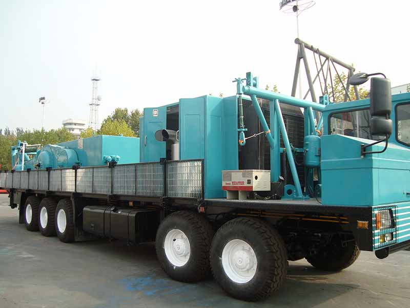
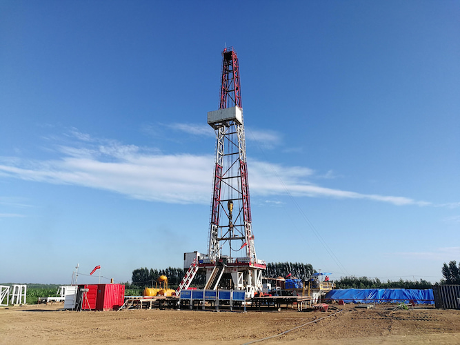
An oil drilling rig is a large-scale mechanical equipment used in oil and gas drilling operations. Its main function is to drive drilling tools to break underground rocks and drill wellbores, providing channels for subsequent exploitation and thereby realizing the exploration and development of oil and gas resources. Its core functions include hoisting and lowering drilling tools, rotary drilling, and circulating well cleaning. It is mainly composed of power machines, transmission mechanisms, working machines, and auxiliary equipment. Classified by operation scenarios, it can be divided into onshore oil drilling rigs and offshore oil drilling rigs, which are key infrastructure for ensuring global oil and gas supply.
Core Component Systems
A drilling rig consists of eight major systems: the hoisting system controls the lifting and lowering of drilling tools via drawworks and pulley blocks; the rotary system drives the drill bit to break rock formations; the circulation system uses high-pressure mud to remove cuttings; the power and transmission system provides power distribution; the control system coordinates equipment operation; the derrick and substructure provide support; and auxiliary equipment includes safety devices such as blowout preventers (BOP). Core components include the derrick, crown block, rotary table, and various types of drill bits. Top drive drilling rigs adopt top drive (power swivel) technology, which improves drilling efficiency and is suitable for deep well operations. During operation, mud pumps circulate mud to cool the drill bit, and braking mechanisms adjust drilling parameters.
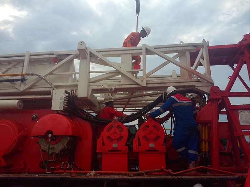
Ⅰ. Hoisting System
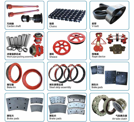
The hoisting system is equipped to hoist and lower drilling tools, run casing, control weight on bit (WOB), and feed drilling tools. It includes the drawworks, auxiliary brakes, crown block, traveling block, hook, wire rope, and various tools such as elevator links, elevators, tongs, and slips.
When hoisting, the drawworks drum winds the wire rope; the crown block and traveling block form a secondary pulley system. The hook rises to lift the drilling tools through tools like elevator links and elevators. When lowering, the drilling tools or casing string descends by its own weight, and the lowering speed of the hook is controlled by the drawworks' braking mechanism and auxiliary brakes. During normal drilling, the feed speed of the drilling tools is controlled by the braking mechanism, and a portion of the drilling tool weight is applied to the drill bit as WOB to break rock formations.
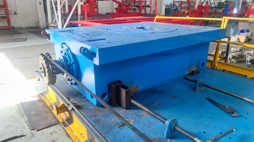
Ⅱ. Rotary System
The rotary system is a typical system of a rotary table drilling rig, whose role is to drive the drilling tools to rotate for breaking rock formations. It includes the rotary table, swivel, and drilling tools. The composition of drilling tools varies depending on the type of well being drilled; generally, it includes the kelly, drill pipe, drill collars, and drill bit, as well as stabilizers, shock absorbers, and adapter subs.
Among them, the drill bit is the tool that directly breaks rock. Drill collars have high weight and wall thickness, used to apply WOB to the drill bit. Drill pipes connect surface equipment and downhole equipment and transmit torque. The kelly typically has a square cross-section; the rotary table drives the entire drill string and drill bit to rotate via the kelly. The swivel is a typical component of a rotary drilling rig: it not only bears the weight of the drilling tools but also enables rotational movement, while providing a channel for high-pressure mud.
Ⅲ. Circulation System
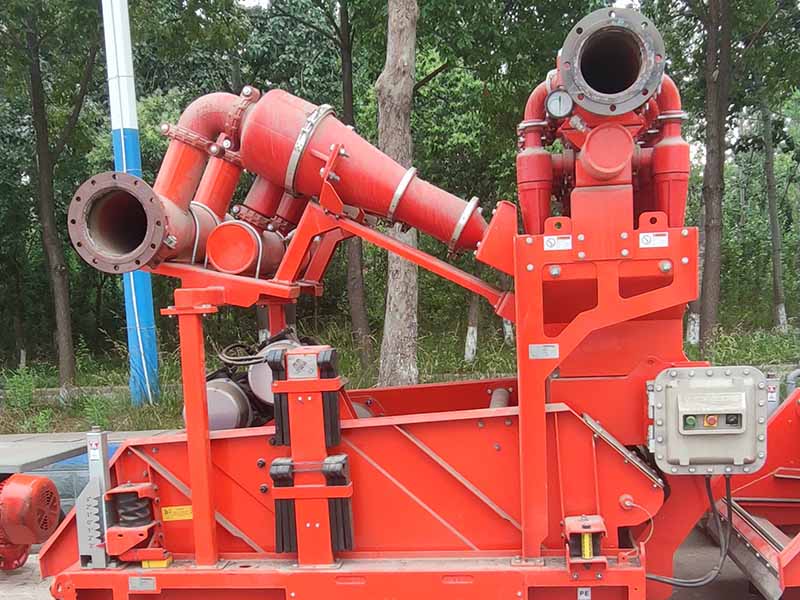
The rotary drilling rig is equipped with a circulation system to promptly carry cuttings broken by the downhole drill bit to the surface for continuous drilling, while cooling the drill bit, protecting the wellbore, and preventing drilling accidents such as wellbore collapse and lost circulation.
The circulation system includes mud pumps, surface manifolds, mud tanks, and mud purification equipment. The surface manifolds include high-pressure manifolds, standpipes, and hose lines; the mud purification equipment includes shale shakers, desanders, desilters, and drilling mud centrifuges.
The mud pump suctions mud from the mud tank; the mud, after being pressurized by the mud pump, flows through the high-pressure manifold, standpipe, and hose line, enters the swivel, and is lowered to the bottom of the well through the hollow drilling tools. It is ejected from the nozzles of the drill bit, then carries cuttings back to the surface through the annular space between the wellbore and the drilling tools. The mud returned from the bottom of the well passes through various levels of mud purification equipment to remove solid content, and then is reused.
Ⅳ. Power Equipment
The hoisting system, circulation system, and rotary system are the three major working units of the drilling rig, used to provide power. Their coordinated operation enables drilling operations. To supply power to these working units, the drilling rig needs to be equipped with power equipment. The power equipment of a drilling rig includes diesel engines, AC motors, and DC motors.
Ⅴ. Transmission System
The transmission system converts the force and motion provided by the power equipment, then transmits and distributes them to each working unit to meet the different power requirements of each unit. The transmission system generally includes a reduction mechanism, speed change mechanism, forward/reverse mechanism, and a coupling mechanism between multiple power machines.
Ⅵ. Control System
To ensure the coordinated operation of the three major working units of the drilling rig and meet the requirements of drilling technology, the drilling rig is equipped with a control system. Control methods include mechanical control, pneumatic control, electrical control, and hydraulic control.
The commonly used control method on drilling rigs is centralized pneumatic control. The driller can complete almost all drilling rig controls through the driller's console on the rig, such as engaging/disengaging the main clutch; coupling multiple power machines; starting/stopping the drawworks, rotary table, and mud pumps; and controlling the high/low speed of the drawworks.
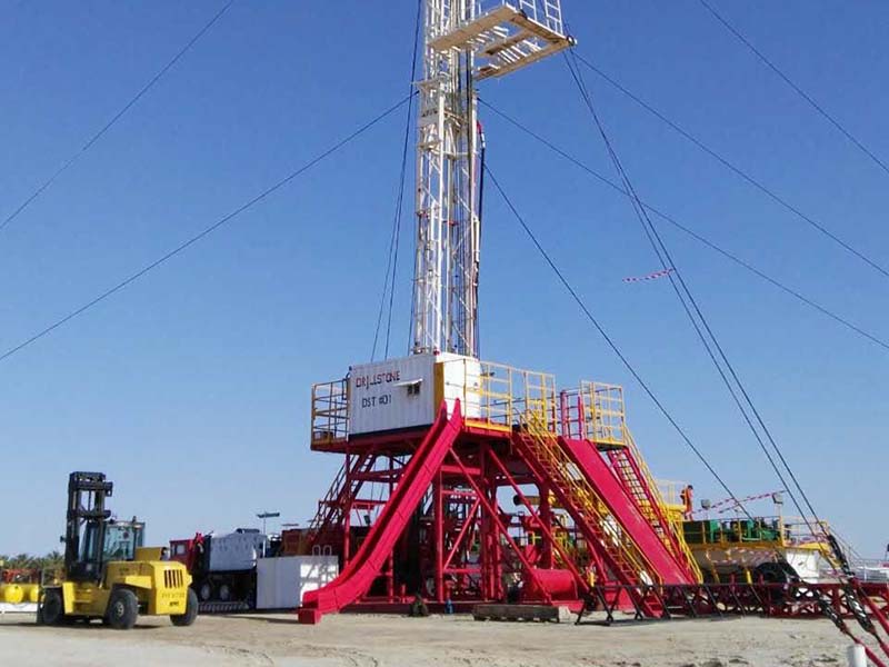
Ⅶ. Derrick and Substructure
The derrick and substructure are used to support and install various drilling equipment and tools, and provide a drilling operation site. The derrick is used to install the crown block, suspend the traveling block, hook, swivel, and drilling tools, bear drilling workloads, and stack stands. The substructure is used to install the power unit, drawworks, and rotary table, support the derrick, suspend the drilling tools via the rotary table, and provide height space between the rotary table and the ground for installing necessary BOPs and facilitating mud circulation.
Ⅷ. Auxiliary Equipment
To ensure the safety and normal progress of drilling, the drilling rig also includes other auxiliary equipment, such as a BOP stack for preventing blowouts, a generator set for providing lighting and auxiliary power for drilling, an air compression device for supplying compressed air, and water supply and oil supply equipment.
Read More


 Language :
 English
 Русский
 عربي
عربي
 GET A QUOTE


 IPv6 network supported