Analysis of Common Failures in Mud Pump Crosshead Assembly
Aug 29, 2025
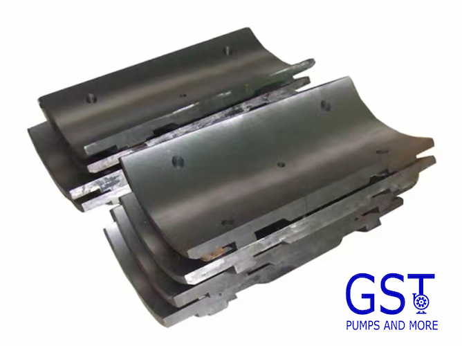
The mud pump crosshead assembly is a core connecting component in the power transmission system of triplex single action mud pumps, which are widely used in oil drilling, geological exploration, and other fields. It undertakes the key functions of "rotational motion-linear motion conversion" and "high-pressure load transmission", directly determining whether the mud pump can stably output high-pressure drilling fluid. As one of the core assemblies ensuring continuous and safe drilling operations, it is extensively applied in onshore oil and gas drilling, offshore drilling, and mineral exploration sites.
Ⅰ. Core Functions
The mud pump realizes the suction and discharge of drilling fluid through the transmission chain of "crankshaft → connecting rod → crosshead assembly → piston rod". As a key intermediate node, the crosshead assembly’s core functions can be summarized into three aspects:
1.Motion Form Conversion: It receives the crankshaft’s circular motion transmitted by the connecting rod, and through the precise cooperation between the crosshead slide and the pump body guide rail, converts the rotational power into the axial linear motion of the piston rod. This ensures the piston in the mud pump fluid end module reciprocates with a fixed stroke, avoiding displacement fluctuations.
2.High-Pressure Load Transmission & Buffering: It bears two key types of loads——first, the reciprocating inertial force generated by crankshaft rotation; second, the reaction force formed by high-pressure drilling fluid in the mud pump fluid end module. Through its rigid structure, it evenly distributes the load to the pump body, preventing the piston rod and connecting rod from breaking due to local stress concentration.
3.Motion Guidance & Centering: Relying on the strict clearance control between the crosshead slide and the guide rail, it restricts the radial runout of the piston rod, ensuring the piston reciprocates centrally in the mud pump fluid end module This prevents eccentric wear between the piston and the cylinder liner (eccentric wear can lead to cylinder liner seal failure, requiring frequent replacement and increasing operation costs).
Ⅱ. Industry Adaptation Standards & Common Failures
The crosshead assembly must match the mud pump model (e.g., Model F-1600, F-2200). Key parameters include: crosshead body stroke, connecting rod pin diameter (usually 50-80mm, increasing with pump size), and slide dimensions (adapting to the pump body guide rail). It must also comply with the strength and wear resistance requirements for "power end components" specified in API Spec 7K, ensuring a service life of ≥5000 hours under high-pressure and high-frequency working conditions.
As a core power transmission component, the mud pump crosshead assembly operates long-term under high pressure (35-70MPa), high-frequency reciprocation, and dust/mud contamination. It is prone to failures caused by poor lubrication, excessive wear, assembly deviation, etc. Combined with on-site oil drilling practices, the following section outlines the phenomena, causes, and targeted solutions for several typical failures, all in line with API Spec 7K industry standards.
1.Crosshead Slide Cylinder Scuffing
Fault Phenomena
A sharp friction sound occurs when the mud pump operates, followed by a sudden rise in the power end temperature (slide area exceeds 60℃);
In severe cases, the piston rod seizes, pump displacement drops sharply or the pump shuts down. Disassembly reveals metal scratches and local fusion welding on the contact surface between the slide and the guide rail.
Fault Causes
Lubrication Failure: Insufficient pressure of the lubricating oil pump (<0.2MPa), blocked oil passages, or incorrect lubricating oil type, leading to dry friction between the slide and the guide rail;
Assembly Deviation: Excessively small fit clearance between the slide and the guide rail (<0.05mm), or excessive misalignment of the crosshead, causing extrusion friction during motion;
Contaminant Invasion: Damaged dust seals allow mud and dust to enter the gap between the slide and the guide rail, resulting in "abrasive wear".
Solutions
Emergency Treatment: Shut down the pump immediately, remove the power end cover, clean residual oil stains and metal debris from the surfaces of the slide and guide rail, and check if the guide rail is deformed;
Component Replacement: If the slide has obvious scratches or fusion welding, replace the slide entirely; if the guide rail is scratched, repair it by grinding with fine sandpaper, and replace the guide rail if damage is severe;
System Inspection: Clean the lubricating oil passages (flush with high-pressure oil), check the lubricating oil pump pressure (adjust to 0.2-0.4MPa), replace damaged dust seals, and replenish lubricating oil that meets standards;
Reassembly: Adjust the fit clearance between the slide and the guide rail (0.05-0.1mm), and calibrate the crosshead alignment (use a dial indicator to measure the piston rod’s radial runout, ensuring it is ≤0.05mm).
2. Connecting Rod Pin Fracture
Fault Phenomena
A sudden impact sound occurs when the mud pump operates, followed by intensified vibration of the power end and complete interruption of displacement;
Disassembly reveals the connecting rod pin is fractured either in the middle or at the joint with the crosshead body, with fatigue cracks on the fracture surface.
Fault Causes
Fatigue Damage: Substandard material of the connecting rod pin, heat treatment defects, or long-term exposure to reciprocating inertial forces, leading to fatigue cracks on the fracture surface;
Improper Assembly: Excessively loose fit between the connecting rod pin and the crosshead body pin hole (clearance >0.03mm), causing radial runout during operation and increasing local stress; or the elastic retainer ring is not installed in place, leading to axial displacement of the connecting rod pin and uneven force bearing;
Overload: The mud pump operates under overpressure during drilling (outlet pressure >10% of the rated pressure), or frequent pressure buildup in the mud pump fluid end module, causing the connecting rod pin to bear instantaneous impact loads.
Solutions
Component Replacement: Replace the connecting rod pin with one that meets standards, and check if the small end hole of the connecting rod is worn;
Assembly Calibration: Ensure a transition fit between the connecting rod pin and the crosshead body pin hole, with the clearance controlled at 0.01-0.03mm; the elastic retainer ring must be fully snapped into the groove to prevent axial runout;
Working Condition Control: Adjust the mud pump outlet pressure to the rated range (refer to pump parameters, e.g., Model F-1600 pump has a rated pressure of 35MPa). Strengthen monitoring of the mud circulation system during drilling to avoid pressure buildup in the mud pump fluid end module;
Regular Inspection: Conduct magnetic particle inspection on the connecting rod pin surface every 500 hours to check for fatigue cracks, and replace components with potential hazards in advance.
3. Uneven Reciprocation of Piston Rod
Fault Phenomena
Significant fluctuations in mud pump displacement, unstable upward return of drilling fluid, which may lead to incomplete wellbore cleaning;
Disassembly reveals looseness at the connection between the piston rod and the crosshead body, or excessive clearance (>0.1mm) between the slide and the guide rail.
Fault Causes
Excessive Slide Wear: Reduced thickness of the slide after long-term use (wear exceeding 0.2mm), leading to excessive fit clearance with the guide rail and radial runout of the crosshead during reciprocation;
Loose Connection: The thread of the piston rod connecting sleeve is not tightened, causing thread loosening during operation and misalignment between the piston rod and the crosshead;
Guide Rail Deformation: Long-term vibration and impact on the pump body cause local bending of the guide rail (straightness exceeding 0.05mm/m), leading to deviation of the guidance trajectory.
Solutions
Slide Handling: Measure the slide thickness; replace slides in pairs when wear exceeds the limit. If the clearance is slightly large (0.1-0.15mm), adjust by adding thin copper gaskets (thickness 0.03-0.05mm) on the back of the slide;
Connection Tightening: Remove the piston rod connecting sleeve, clean oil stains on the thread surface, retighten the thread, and install lock washers or perform spot welding for anti-loosening;
Guide Rail Repair: Use a dial indicator to check the guide rail straightness; repair slight deformation by grinding with a grinder; replace the pump body guide rail if deformation is severe, ensuring the guide rail straightness is ≤0.03mm/m;
Alignment Calibration: Recalibrate the coaxiality of the piston rod and the crosshead, controlling the deviation at ≤0.05mm to avoid force deviation during reciprocation.
4. Lubricating Oil Leakage
Fault Phenomena
Lubricating oil seeps out from the crosshead area (junction of the power end and hydraulic end) and drips into the drilling fluid circulation system, causing drilling fluid contamination;
The oil level in the lubricating oil tank drops rapidly, requiring frequent oil replenishment and increasing maintenance costs.
Fault Causes
Seal Failure: Aging or deformation of O-rings, or damaged dust seals, leading to lubricating oil seepage from the seal gap;
Oil Retaining Ring Damage: The oil retaining ring on the crosshead body falls off or cracks, failing to block the flow of lubricating oil to the hydraulic end;
Excessive Oil Passage Pressure: The lubricating oil pump pressure exceeds 0.4MPa, exceeding the bearing capacity of the seals and causing lubricating oil to be squeezed out from the seal area.
Solutions
Seal Replacement: Disassemble the crosshead assembly, replace aging O-rings and dust seals, and apply lubricating oil to the seal surface before installation;
Oil Retaining Ring Repair: Reinstall the oil retaining ring, ensuring it is snapped into the groove of the crosshead body; replace the oil retaining ring with the same model if it is cracked;
Pressure Adjustment: Adjust the lubricating oil pump pressure to 0.2-0.4MPa, and check if the pressure relief valve is functioning properly (disassemble, clean, or replace the pressure relief valve if it is stuck);
Contamination Treatment: Clean the leaked lubricating oil, test the oil content of the drilling fluid, and add drilling fluid oil remover if the oil content exceeds the limit to avoid affecting drilling fluid performance.
5. Poor Contact Between Slide and Guide Rail
Fault Phenomena
Friction sound occurs at the slide area when the mud pump operates, and the power end temperature is slightly elevated;
After disassembly, inspection shows the contact area between the slide and the guide rail is <80%, with local "bright spots" (virtual contact) where no contact occurs.
Fault Causes
Assembly Deviation: The slide is not aligned with the guide rail during installation, or the guide rail surface is uneven (machining error >0.02mm);
Slide Deformation: Substandard slide material leads to slight deformation of the slide after long-term heating, reducing the fit degree of the contact surface;
Insufficient Lubrication: Uneven oil supply in the lubricating oil passage causes local lack of lubricating oil on the slide, forming "dry friction areas" and affecting contact performance.
Solutions
Grinding Repair: Disassemble the slide and guide rail, manually grind the guide rail surface with fine abrasive sand until the surface roughness Ra ≤0.8μm; grind the slide contact surface using the same method, ensuring the contact area is ≥80%;
Reassembly: Calibrate the slide position with a dial indicator during installation, ensuring the parallelism deviation between the slide and the guide rail is ≤0.01mm/m;
Lubrication Optimization: Clean the lubricating oil passage, check if the oil injection nozzle is unobstructed, and ensure lubricating oil evenly covers the contact surface between the slide and the guide rail; if necessary, install a throttle valve in the slide oil passage to adjust the oil supply;
Material Inspection: Verify the material of new slides to avoid using low-quality slides.
Ⅲ.Summary
Prioritize Lubrication: Check the lubricating oil pressure and oil level daily; replace lubricating oil regularly (every 2000 hours); ensure the lubrication system is free of blockages and leaks;
Regular Inspection: Disassemble and inspect the crosshead assembly every 500-800 hours, focusing on slide wear, connecting rod pin fatigue, and seal aging; use flaw detection equipment to check for cracks;
Standardized Assembly: Strictly follow API Spec 7K standards for assembly; control fit clearances (e.g., slide-guide rail: 0.05-0.1mm, connecting rod pin-pin hole: 0.01-0.03mm); ensure alignment;
Working Condition Control: Avoid overpressure and overspeed operation of the mud pump to prevent instantaneous impact loads from damaging components.
Read More


 Language :
 English
 Русский
 عربي
عربي
 GET A QUOTE


 IPv6 network supported