facebook linkedin youtube whatsapp
National Unified Hotline :

+86 22 5807 5652

Email Us :

gm@geostarpe.com

#Language :

EnglishEnglish

内页banner

Search

Home

drill collar

  • What is the rotary system of a drilling rig?
    What is the rotary system of a drilling rig?
    Sep 26, 2025
    The rotary system is a typical component of a rotary drilling rig, whose function is to drive the drill string to rotate for rock breaking. It consists of the rotary table, swivel, and drill tools. The composition of drill tools varies depending on the type of well being drilled; generally, they include the kelly, drill pipe, drill collar, and bit, along with accessories such as stabilizers, shock absorbers, and adapter subs. Among these, the bit is the tool that directly breaks rock. The drill collar, featuring high weight and thick wall, is used to apply weight on bit (WOB). The drill pipe connects surface equipment to downhole equipment and transmits torque. The kelly typically has a square cross-section; the rotary table drives the entire drill string and bit to rotate via the kelly. The swivel is a classic component of rotary drilling rigs, which not only bears the weight of the drill tools and enables rotational movement but also provides a channel for high-pressure mud. Ⅰ. Key Components Rotary Table Composed of horizontal bearings, bevel gears, square kelly bushing (SKB), and a housing, it mostly adopts a gear transmission structure. 1.Serves as the executive core of the rotary system, driving the kelly or drill string to rotate through gear transmission; 2.Provides wellhead support and bears part of the drill string weight; 3.The square kelly bushing (SKB) fixes the kelly to ensure stable torque transmission. Swivel Consists of a gooseneck, center pipe, rotating bearings, sealing devices, and a suspension assembly. Its top is connected to the hook, and the bottom is connected to the kelly. 1.When the hook and traveling block are stationary, the swivel drives the kelly to rotate while preventing drilling fluid leakage; 2.The gooseneck is connected to the drilling fluid pipeline, and the center pipe guides the drilling fluid into the drill string; 3.Bears part of the drill string weight through the suspension assembly and coordinates with the hoisting system to adjust WOB. Kelly A thick-walled steel pipe with a square or hexagonal cross-section, usually 9-12 meters in length, with drill pipe joints at both ends. 1.Its upper end is connected to the swivel, and the lower end is connected to the drill string via a drill pipe joint, transmitting torque from the rotary table or top drive to the downhole drill string; 2.Its square cross-section matches the square kelly bushing of the rotary table to prevent slipping during rotation. Top Drive Composed of an electric motor (or hydraulic motor), gearbox, main shaft, drill pipe make-up/break-out device, and drilling fluid channel, it is installed below the traveling block. 1.Can directly drive the drill string to rotate without frequent joint making-up (reducing tripping time); 2.Equipped with a built-in make-up/break-out device, it can automatically tighten and loosen drill pipe threads, improving operational efficiency; 3.Suitable for deep wells, ultra-deep wells, and extended-reach wells, reducing drill string fatigue damage. Ⅱ. Core Functions Torque Provision Converts the energy of power equipment into the rotational torque of the drill string, driving the bit to rotate at high speed (typically 30-150 r/min) and enabling the bit cones to break rock formations. Drilling Fluid Circulation Support The rotary table and swivel of the rotary system are equipped with central through-holes. Drilling fluid can be injected into the drill string through these holes and finally sprayed out from the bit nozzles, fulfilling three key roles: cuttings carrying, bit cooling, and drill tool lubrication. Drill String Centering Maintenance Through the positioning function of components such as the rotary table and kelly bushing, it ensures the drill string always moves along the central axis of the wellbore during rotation, preventing wellbore deviation caused by drill string offset (especially critical for vertical well drilling). Downhole Tool Compatibility Can be compatible with directional drilling tools (e.g., progressive cavity drillers (PCD), measurement while drilling (MWD) tools). By adjusting the rotation speed or coordinating with downhole power tools, it achieves precise control of the wellbore trajectory (e.g., deviation building and hold for horizontal wells). Ⅲ. Working Principle Torque Transmission Process Diesel engine/Electric motor → Gearbox → Bevel gears → Rotary table rotation → Square kelly bushing driving kelly rotation → Kelly transmitting torque to downhole drill string via drill pipe joint → Bit rotating to break rock. Drilling Fluid Circulation Process Drilling pump → High-pressure pipeline → Swivel gooseneck → Swivel center pipe → Kelly → Inside of drill string → Bit nozzles → Annular space of wellbore → Wellhead return → Mud tank (for cuttings separation and recycling). Ⅳ. Daily Maintenance Rotary Table: Regularly clean the gearbox, replenish gear oil, and inspect bearing wear; Swivel: Clean the center pipe after each tripping operation and check the lubrication status of rotating bearings; Top Drive: Regularly calibrate the torque sensor, and inspect the motor insulation performance and hydraulic system pressure.
    Read More
  • What is a directional well in oil drilling?
    What is a directional well in oil drilling?
    Sep 17, 2025
    Directional drilling technology is one of the most advanced drilling technologies in the global oil exploration and development field today. It relies on special downhole tools, measurement instruments, and process technologies to effectively control the wellbore trajectory, guiding the drill bit to reach the predetermined underground target along a specific direction. This technology breaks the limitation of vertical wells, which "can only develop resources directly below the wellhead". By adopting directional drilling technology, oil and gas resources restricted by surface or underground conditions can be developed economically and effectively, significantly increasing oil and gas production and reducing drilling costs. In essence, a directional well is a drilling method that guides the wellbore to reach the target formation along a pre-designed deviation angle and azimuth. There are three main types of its well profiles: (1) Two-section type: Vertical section + build-up section; (2) Three-section type: Vertical section + build-up section + tangent section; (3) Five-section type: Upper vertical section + build-up section + tangent section + drop-off section + lower vertical section A horizontal well is a type of directional well. Conventional oil wells penetrate the oil reservoir vertically or at a shallow angle, resulting in a short wellbore section passing through the reservoir. In contrast, after drilling vertically or at an angle to reach the oil reservoir, the wellbore of a horizontal well is turned to a near-horizontal direction to remain parallel to the oil reservoir, allowing long-distance drilling within the reservoir until completion. Equipped with high-strength heavy-weight drill pipes (HWDP) for horizontal sections and wear-resistant PDC (Polycrystalline Diamond Compact) bits, the length of the reservoir-penetrating section can range from hundreds of meters to over 2,000 meters. This not only reduces the flow resistance of fluids entering the well but also increases production capacity several times compared to conventional vertical or deviated wells, facilitating enhanced oil recovery. Ⅰ. Application Scenarios 1. Overcoming Surface/Underground Obstacles Surface obstacles: When there are buildings, railways, lakes, or ecological protection zones above the reservoir, directional wells can be drilled outside these obstacles to reach the reservoir at an angle (e.g., development of oil and gas reservoirs around cities). Underground obstacles: When bypassing hazardous geological features such as underground caves, salt domes, and faults, shock-resistant and collapse-proof drill collars and high-pressure blowout preventers (BOP) are used in coordination to avoid drilling accidents like pipe sticking and blowouts. 2. Enhancing Production Capacity of Unconventional Oil and Gas Reservoirs Unconventional reservoirs such as shale gas and tight oil have "extremely low permeability". Vertical wells can only access a small area of the reservoir, leading to limited production capacity. However, horizontal wells traverse the reservoir horizontally over a distance of several hundred meters, increasing the contact area with the reservoir by dozens of times. The daily gas production of a single horizontal well can be 5 to 10 times that of a vertical well, making it a core technology for unconventional oil and gas development. 3. Reducing Development Costs Offshore oil and gas fields: Drilling a cluster of wells from a single offshore platform is far less costly than building a separate platform for each target, resulting in a 30% to 50% reduction in development costs. Mature oil fields: Through "sidETracking" of directional wells (drilling branches from the wellbore of an old well to develop remaining oil reservoirs in the surrounding area), there is no need to drill new vertical wells, significantly reducing investment. Ⅱ. Advantages and Disadvantages Compared with Vertical Wells Advantages 1.Strong resource coverage capability: It can develop offset reservoirs and scattered reservoirs that are inaccessible to vertical wells, improving the production efficiency of oil and gas reservoirs. 2.High single-well production capacity: Horizontal wells, in particular, greatly increase the contact area between the wellbore and the reservoir, offering significant advantages in the development of unconventional oil and gas reservoirs. 3.Superior cost-effectiveness: Cluster wells and multi-lateral wells, supported by integrated drilling rigs and matched drilling equipment (such as top drives and mud pumps), reduce surface occupation and platform construction costs, making them suitable for offshore and intensive development scenarios. Disadvantages 1.High technical complexity: It requires professional directional drillers, rotary steerable systems (RSS), and MWD (Measurement While Drilling) equipment, resulting in a much higher technical threshold than vertical wells. 2.High costs: The investment in a single directional well is usually 20% to 50% higher than that of a vertical well of the same depth (due to increased costs of tools, equipment, and labor). 3.High risks: The complex trajectory leads to high circulating resistance of drilling fluid and increased difficulty in wellbore stability, resulting in a higher incidence of accidents such as pipe sticking and wellbore collapse compared to vertical wells. 4.Long construction cycle: Frequent trajectory adjustments and data measurements are required, leading to a 30% to 60% longer construction cycle than vertical wells of the same depth. Ⅲ. Conclusion In summary, directional drilling represents a milestone in the evolution of oil drilling from simple vertical development to complex and precise development. Currently, in global oil and gas resource development, the application proportion of directional wells has exceeded that of vertical wells, making it one of the core technologies for ensuring oil and gas supply.
    Read More
  • What is a drill string stabilizer?
    What is a drill string stabilizer?
    Aug 08, 2025
    The Drill String Stabilizer is a critical tool installed on the drill string in oil and gas drilling, geological exploration, and other engineering projects. Its primary functions include stabilizing the drill string, controlling wellbore trajectory, reducing drill string vibration and wear, and ensuring efficient and safe drilling operations. Below is a detailed introduction: I. Core Functions Stabilizing the drill string and preventing deviationThrough contact with the wellbore wall, the stabilizer provides radial support for the drill string, reducing lateral oscillation of the drill string during rotation and drilling. This prevents the wellbore from deviating from the designed trajectory (e.g., trajectory control in directional or horizontal wells). Controlling wellbore diameterThe outer diameter of the stabilizer is close to that of the drill bit, allowing it to scrape excess rock or mud cake from the wellbore wall. This ensures a regular wellbore shape, prevents wellbore enlargement or shrinkage, and creates favorable conditions for subsequent cementing and completion operations. Reducing drill string wear and fatigueIt minimizes friction between the drill string and the wellbore wall, reduces bending and vibration of drill pipes and drill collars, extends the service life of drill tools, and lowers the risk of accidents such as drill string breakage and sticking. Optimizing hydraulic performanceSome stabilizers are designed with diversion grooves or water eyes, which improve the flow path of drilling fluid, enhancing sand-carrying capacity and the efficiency of bit cooling. II. Main Classifications and Structural Features Drill string stabilizers can be categorized based on structural design, application scenarios, and stabilization principles: Classified by Structural Form Integral Stabilizer Structure: Forged from a single piece of steel (e.g., alloy steel) and machined, with ribs integrated into the main body (no welded or assembled components). Features: High strength and impact resistance, suitable for deep wells, hard formations, or high-rotational-speed drilling scenarios. Application: Deep well drilling, hard rock formations, and high-build-rate sections of directional wells. Insert-type Stabilizer Structure: Hard alloy inserts (e.g., tungsten carbide teeth) or polycrystalline diamond compact (PDC) inserts are embedded in the ribs of the main body. Features: Exceptional wear resistance, effectively handling abrasive formations (e.g., sandstone, conglomerate) and extending service life. Application: Abrasive formations and horizontal well sections (requiring long-term contact with the wellbore wall). Replaceable Sleeve Stabilizer Structure: The main body serves as a base, with a detachable wear-resistant alloy sleeve for stabilization. Worn sleeves can be replaced without discarding the entire body. Features: Cost-effective, reducing maintenance costs, suitable for medium to low abrasive formations. Application: Conventional vertical wells and secondary/multiple use requirements in medium-deep wells. Spiral Stabilizer Structure: Ribs are distributed in a spiral pattern, minimizing contact area with the wellbore wall and ensuring smoother fluid passage. Features: Reduces drilling fluid flow resistance and pressure loss, while providing both stabilization and diversion functions. Application: High-displacement drilling and horizontal sections (reducing cuttings bed accumulation). Classified by Installation Position Near-bit Stabilizer: Installed closest to the drill bit (typically 0.5–3 meters above the bit), directly controlling bit deviation and serving as the core tool for trajectory control. Middle Stabilizer: Installed in the middle of the drill string to assist in stabilizing the string and reducing overall bending deformation. Top Stabilizer: Located near the wellhead or rotary table, primarily preventing oscillation of the drill string near the wellhead. 
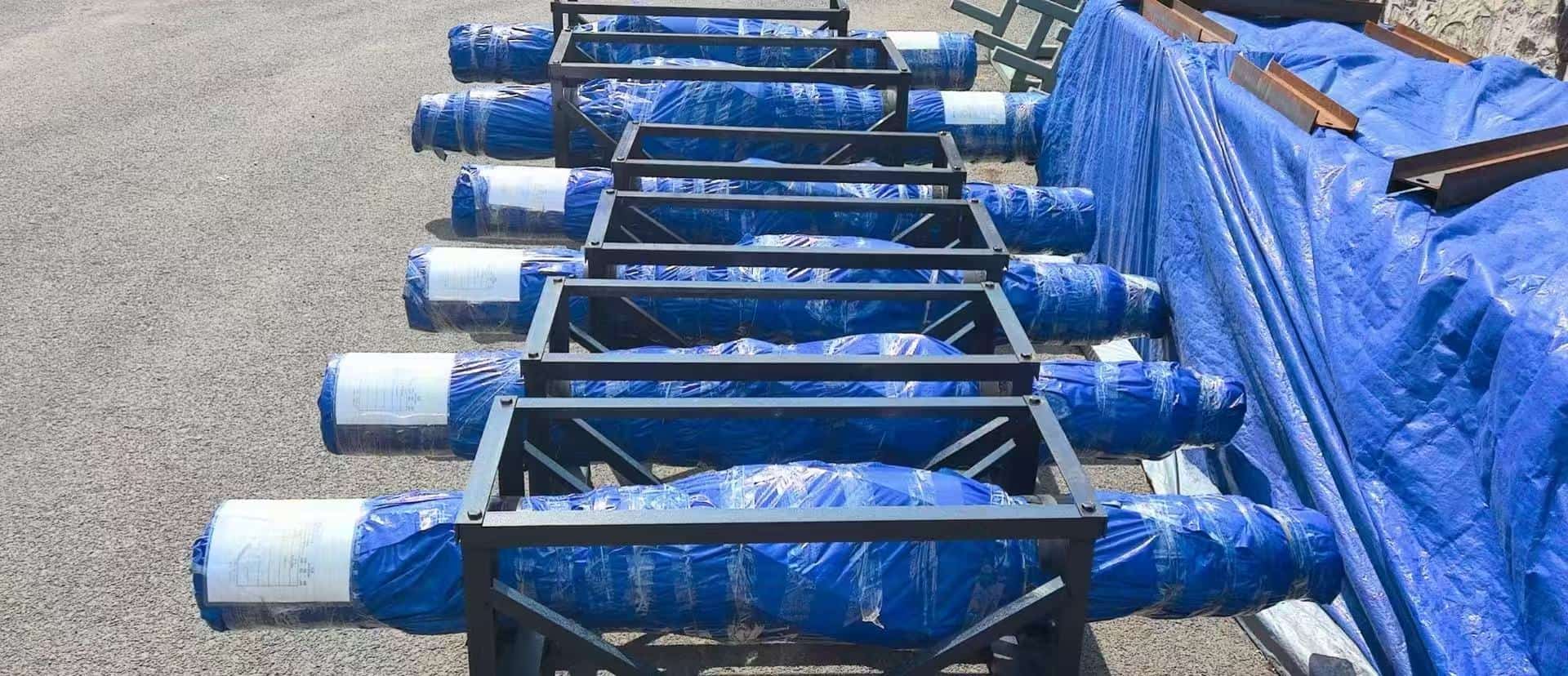
III. Structural Composition Drill string stabilizers typically consist of the following components: Main Body: A cylindrical metal structure, usually made of high-strength alloy steel, with wear and impact resistance. Stabilizing Ribs (Blades): Protruding structures evenly distributed around the circumference of the main body (commonly 3–6 ribs). These are the core contact points with the wellbore wall, with rib shape and quantity designed based on drilling requirements. Connection Threads: Equipped with drill pipe threads (e.g., API standard threads) at both ends for connection to the drill string (drill collars, drill pipes). Diversion Grooves: Grooves between the blades for drilling fluid circulation. Some designs optimize groove geometry to reduce pressure loss. IV. Key Technical Parameters Outer Diameter: Matches the wellbore size, typically 3–5mm smaller than the wellbore diameter (e.g., a 215.9mm wellbore uses a 210mm stabilizer), ensuring stabilization while avoiding sticking risks. Number of Ribs: Commonly 3, 4, or 6 ribs. More ribs improve stability but may increase drilling fluid flow resistance. Length: Designed based on well section requirements. Near-bit stabilizers are usually shorter (0.5–1.5 meters), while middle stabilizers can be longer (1–3 meters). Material: Main Body: Mostly high-strength alloy steels such as 4145H or 4140H, tempered to provide good toughness and fatigue resistance. Wear-resistant Components: Tungsten carbide (WC-Co), PDC inserts, ceramic coatings, etc., to enhance wear resistance. Maximum Operating Pressure/Temperature: Designed to withstand high-temperature and high-pressure environments in deep wells. Conventional products tolerate temperatures ≥150°C and pressures ≥30MPa. V. Application Scenarios and Selection Principles Formation Characteristics Soft Formations: Prioritize spiral or integral stabilizers to minimize formation disturbance. Hard/Abrasive Formations: Insert-type stabilizers are mandatory to prevent rapid wear. Well Type Requirements Vertical Wells: Focus on deviation control, selecting high-stability integral or 4-rib stabilizers. Directional/Horizontal Wells: Near-bit stabilizers require high-precision design, paired with spiral structures to reduce cuttings accumulation. Drilling Parameters High rotational speed (≥150rpm) drilling requires integral stabilizers with strong fatigue resistance.High-displacement drilling prioritizes spiral structures. VI. Application Considerations Selection Adaptation: Choose the appropriate stabilizer type based on formation hardness, well type (vertical/directional/horizontal), and drilling fluid properties. Installation Position: Typically installed above the bit near the drill collar, or spaced according to drill string design to form a "full-hole drill string" structure. Maintenance Inspection: Regularly check rib wear and thread integrity to avoid wellbore deviation or drill string damage due to stabilizer failure. Coordination with Other Tools: Work synergistically with bits, drill collars, shock absorbers, etc., to optimize overall stability of the drill string assembly. VII. Usage and Maintenance Guidelines Pre-run Inspection Check rib wear (replace if wear exceeds design limits). Inspect the main body for cracks, deformation, or thread damage. Ensure inserts are not loose or missing, and spiral channels are unobstructed. In-use Monitoring Real-time monitoring of torque and weight-on-bit fluctuations; anomalies may indicate stabilizer failure. Regularly evaluate wellbore trajectory using Measurement While Drilling (MWD) data to verify stabilizer effectiveness. Maintenance Clean residual drilling fluid after use and inspect wear on critical components. Replace worn inserts for insert-type stabilizers and timely replace sleeves for replaceable sleeve stabilizers.   The drill string stabilizer achieves the core goal of "stable drill string – regular wellbore – efficient drilling" through three synergistic functions: rigid support to suppress drill string oscillation, trajectory constraints to control wellbore direction, and hydraulic optimization to enhance sand-carrying and cooling efficiency. Its performance directly impacts drilling safety, wellbore quality, and operational costs, making it an indispensable tool in complex well drilling (e.g., shale gas horizontal wells, deep wells).
    Read More

Leave A Message

Leave A Message
If you are interested in our products and want to know more details, please leave a message here, we will reply to you as soon as we can.
Submit

Home

Products

whatsApp

contact