How to Improve the Wear Resistance of Mud Pump Liners?
Apr 15, 2026
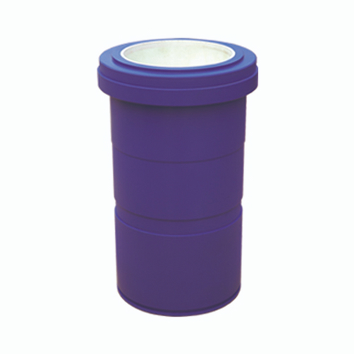
In petroleum drilling operations, the mud pump is critical equipment, and the mup pump liner is the most vital wearable component of the mud pump. Drilling mud is characterized by high sand content, high viscosity, high pressure, and corrosiveness. As the rubber mup pump piston reciprocates at high frequency inside the mup pump liner, the component is subjected to simultaneous wear and corrosion. Failure will directly lead to drilling downtime and reduced exploration efficiency. Improving the wear resistance and service life of mup pump liners has long been a key research topic in the petroleum equipment manufacturing industry.
Ⅰ. Why Do Cylinder Liners Fail Due to Wear?
The mup pump liner and mup pump piston form the core friction pair of the mud pump. The rubber piston reciprocates inside the mup pump liner at a frequency of 90 cycles per minute. When delivering sand-laden mud, the liner faces two major failure mechanisms:
Mechanical Abrasion: Sand particles in the mud, under compression from the piston, continuously abrade the inner bore of the mup pump liner, which is the primary cause of failure.
Chemical Corrosion: The corrosive nature of mud accelerates surface degradation of the mup pump liner, further exacerbating wear.
Industry technical requirements clearly specify: the inner bore surface hardness after induction hardening shall reach 45–50 HRC, with a hardened layer thickness ≥ 0.7 mm. Liners made of 40Cr steel, matched with mud pumps rated at 2.5 MPa, frequently exhibited unsatisfactory performance under traditional processes. Field feedback indicated extremely short service life, severe inner bore wear, and frequent replacement, which severely disrupted drilling operations.
Testing revealed the root cause: finished mup pump liners produced by the traditional process only achieved a hardness of 25–30 HRC and a hardened layer thickness of merely 0.3 mm, far below the required standard.
Ⅱ. The Hardened Layer Is Removed in Traditional Processing
Although the conventional mup pump liner manufacturing process appears complete, it contains a critical defect:
1. Saw cutting → 2. Rough turning (allowance 2–3 mm) → 3. Normalizing heat treatment → 4. Finish turning (inner bore grinding allowance 0.5 mm) → 5. Inner bore induction hardening → 6. Inner bore grinding to final dimension → 7. Warehousing
The problem occurs in the induction hardening + grinding stage. Induction hardening forms a wear-resistant hardened layer on the inner surface, but the subsequent grinding process, intended to ensure dimensional accuracy, removes most of this hardened layer. The final product thus has insufficient hardened layer depth, resulting in drastically reduced wear resistance.
Eliminating grinding entirely preserves the hardened layer but results in out-of-tolerance inner bore dimensions, creating a dilemma: maintaining hardness sacrifices precision, and maintaining precision sacrifices hardness.
Ⅲ. Using Deformation Laws to Achieve Both Hardness and Dimensional Accuracy
Since high-frequency induction hardening causes shrinkage of the inner bore, we have mastered the shrinkage law through experiments.We pre-grind the inner bore to a specific size slightly larger than the drawing dimension before hardening.After quenching, the inner bore shrinks to exactly meet the drawing requirements, while the hardened layer is fully preserved.
1. Optimized Manufacturing Process Flow
Targeted adjustments were made to the traditional process:
1. Saw cutting → 2. Rough turning (allowance 2–3 mm) → 3. Normalizing heat treatment → 4. Finish turning (inner bore grinding reserved, other dimensions finished) → 5. Pre-grinding inner bore to 0.3–0.5 mm over nominal size → 6. Inner bore induction hardening (dimensional recovery via shrinkage) → 7. Warehousing (final grinding eliminated)
2. Key Technology: Controlling Induction Hardening Deformation
To precisely control shrinkage, a precision inner bore inductor was designed. Process parameters were rigorously stabilized through hundreds of trials:
Power: 90–100 kW; Voltage: 10–12 kV
Hardening duration: 40–60 seconds; Liner rotation speed: 40 r/min
A stable shrinkage rule for the inner bore after hardening was finally established.
Ⅳ. Performance Comparison: Wear Resistance Doubled
The performance gap between liners before and after process optimization is evident:
Parameter
Original Process
New Process
Surface Hardness
250–300 HBW (≈25–30 HRC)
50–55 HRC
Hardened Layer Thickness
0–0.3 mm
≥ 0.7 mm
Wear Resistance
Poor, frequent replacement
Improved, service life doubled
Liners manufactured using the optimized process fully meet the technical specifications for hardness and hardened layer depth. Field drilling applications showed a doubled service life, significantly reduced replacement frequency, minimized equipment downtime, and improved operational cost efficiency.
Ⅴ. Four Critical Implementation Guidelines for the New Process
To ensure stable and consistent performance, the following four details are essential:
1. Precise control of the pre-grinding dimension: Strictly following the shrinkage law to control the inner bore size before quenching is the key to ensuring final dimensional accuracy.
2. Dedicated Inductor: A precision inner bore inductor ensures uniform hardened layer depth and consistent hardness.
3. Stable Process Parameters: Strict control of hardening power, duration, and rotation speed guarantees stable bore deformation.
4. Full-Range Dimensional Inspection: Real-time monitoring of inner bore dimensions prevents out-of-tolerance deformation.
Ⅵ. Six Practical Methods to Further Improve Liner Wear Resistance
Beyond core process optimization, we have implemented actionable improvement measures across material selection, surface treatment, and structural design:
1. Material Upgrade
For highly corrosive and abrasive working conditions, upgrade from conventional 40Cr to medium-carbon alloy steels such as 42CrMo and 35CrMo. These grades offer superior hardenability, higher hardness, improved toughness, and significantly enhanced fatigue and wear resistance after quenching.
2. Surface Strengthening Treatment
Optimized Induction Hardening: Besides deformation control, adjust quenching media (specialized quenching oil or polymer solution) to optimize cooling rate, prevent cracking, and improve hardened layer uniformity, ensuring stable hardness of 50–55 HRC around the entire bore.
Nitriding / Carbonitriding: Add a post-hardening nitriding step to form a 0.2–0.3 mm surface layer with hardness exceeding 60 HRC, while improving corrosion resistance and reducing mud-induced corrosive wear.
Laser Cladding / Hardfacing: Deposit wear-resistant alloy powders such as WC (tungsten carbide) or Ni60 on the inner bore, creating a hardened layer above HRC 60. Wear resistance is 3–5 times that of conventional hardened liners, making it ideal for ultra-deep wells and high-sand mud environments.
3. Structural Optimization to Reduce Wear Initiation
Improve Surface Roughness: Reduce inner bore roughness from Ra 1.6 to below Ra 0.8 to minimize micro-asperities, lower frictional resistance during piston reciprocation, and reduce particle-induced abrasive wear.
Optimize Piston-Liner Clearance: Adjust the fit clearance based on mud conditions to avoid mud turbulence and sand erosion from excessive clearance, as well as dry friction from insufficient clearance.
Internal Lubrication Grooves: Add circumferential or spiral lubrication grooves in the inner bore to retain lubricant and form a persistent lubricating film, reducing dry friction and wear rate.
4. Full-Process Heat Treatment Control
Optimized Normalizing: Adjust normalizing temperature and holding time to refine grains and improve matrix homogeneity, providing a sound microstructure for subsequent hardening.
Tempering Operation: Apply low-temperature tempering immediately after hardening to relieve internal stress, prevent deformation and cracking, enhance toughness, and avoid hardened layer spalling.
Full-Range Hardness Inspection: Test inner bore hardness and hardened layer thickness individually after hardening and before finished product warehousing to ensure 100% compliance with 45–55 HRC and ≥ 0.7 mm requirements.
5. Condition Adaptation and Operational Maintenance Optimization
Develop customized process solutions for mud pump liners according to different drilling conditions (shallow wells / deep wells, low sand content / high sand content). For high sand content conditions, the composite strengthening solution of laser cladding + nitriding is preferred.
Upgrade Mud Cleaning Systems: Improve desanding and desilting efficiency to reduce mud sand content, minimizing abrasive wear at the source.
Standardized Installation and Maintenance: Ensure coaxial alignment during mud pump liner installation to prevent mud pump piston side wear. Conduct regular wear inspections and timely replace seals to avoid mud leakage and erosion.
6. Coating Protection for Enhanced Corrosion Resistance
Apply ceramic or PTFE (polytetrafluoroethylene) coatings on the inner bore to create a corrosion-resistant, low-friction protective layer that reduces mud corrosion and lowers friction coefficient.
For highly corrosive drilling muds (such as salt-bearing and acidic muds), a composite solution of stainless steel substrate plus ceramic coating is adopted to comprehensively improve corrosion and wear resistance from the substrate to the surface.
Read More


 Language :
 English
 Русский
 عربي
عربي
 GET A QUOTE


 IPv6 network supported